Filament Thickness Sensors, What Are They And What Are They Good For?

I keep up with the trends in 3D printing reasonably well. The other day my friend mentioned that filament thickness sensing had been added to the latest version of the Marlin firmware. I had no idea what it was, but it certainly sounded cool. I had to find out more.

In industrial settings, filament is made by pulling extruding molten plastic at a certain speed into a cooling bath. The nozzle for 2.85mm filament and 1.75 mm filament is actually the same size, but the filament is stretched more or less as it leaves the nozzle. By balancing these three variables the extrusion machine can produce any size filament desired. Like any mechanical system, it needs constant adjustment to maintain that balance. This is usually done by measuring the filament with a laser after it has cooled, and then feeding this information back into the system. The better filament manufacturers have multiple lasers and very fast feedback loops. Some of the best offer +-0.04mm or less variation in thickness between any two points on the filament. Some of the worst have larger errors such as +-.10mm. Because the plastic is fed into the extruder at a fixed linear speed, this makes a variation in the volume of the plastic coming out of the nozzle per second. With the best we see a 4.41% variation in the volume of plastic extruded. With the worst we start to see 10.51% or more.

FIlament variation showing up as a cosmetic defect.
Filament variation showing up as a cosmetic defect.

A printer is dumb. It works under the assumption that it is getting absolutely perfect filament. So when it gets 10.51% more plastic, it simply pushes it out and continues with its life. However, if the filament is off enough, this can actually show up as a visible defect on the print. Or in worse cases, cause the print to fail by over or under extrusion of plastic.

So, what does a filament thickness sensor do to correct this issue? To start to understand, we need to look at how the filament is dealt with by the software. When the slicer is compiling the G-code for a 3D print, it calculates the volume of plastic it needs in order to deposit a bead of plastic of a certain width and of a certain height per mm of movement. That was a mouthful. For example, when a printer printing 0.2mm layers moves 1mm it wants to put down a volume that’s 1.0mm long x 0.4mm wide x 0.2mm high. The filament being pushed into the nozzle has a volume per mm determined by the diameter of the filament.

(\pi (radius_{filament})^{2}*length_{filament extruded})=volume

The volume out per mm of filament in.

(layer_{height}*layer_{width}*length_{move}) = volume

The equation we are trying to balance.

Our goal is to integrate the thickness sensor into these functions to see what the thickness sensor is doing. This is a linear equation, so there’s nothing fancy here. Now, the layer height, layer width, and length of the move are determined by settings and model geometry respectively. These are fixed numbers so we don’t care about them. That leaves us the diameter of the filament and the length of filament extruded. As we mentioned before, typically the filament is assumed to be a fixed diameter. So all the software has to calculate is the length of filament that needs to be extruded per mm of combined movement in the x and y so that our volumes match.

But, we know that one of these variables is actually changing per millimeter as well. The filament diameter! So now we have a problem. If the filament diameter is changing all the time, our equation will never balance! In order to fix this we can add a multiplier to our equation. Since we have no control over the width of the filament we can’t modify that value. However, if we know the width of the filament, and we know the value its supposed to be, we can change the length of the filament extruded. This is because unlike the filament, we have control over the stepper motor that drives the extruder. This value is called the extrusion multiplier, and its determination is what the thickness sensor is all about.

So all the filament sensor does is measure the filament’s current diameter. It takes expected diameter and divides it by the value it just measured to get a simple percentage. It feeds that number back into our system as the extruder multiplier and slows or speeds up the stepper motor as needed. Pretty simple.
2016-01-26_00h08_00
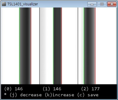
Shadows on the sensor from [inornate]’s variation.
There are a few thickness sensors being toyed with right now. The first, as far as I can tell; let me know if I am wrong in the comments, was by [flipper] on thingiverse. He is in his third version now. The sensor works by casting a shadow of the filament as it passes by onto an optical sensor. The firmware then counts the pixels and works backwards to get the diameter. This value is sent to the Marlin firmware on the printer which does the rest. As is usual and wonderful in the open source community, it wasn’t long before others started working on the problem too. [inoranate] improved on the idea by casting more shadows on the sensor. The technique is still brand new, but it will be interesting to see what benefits it reaps.

Now comes the next question,”Is it worth upgrading my printer with a thickness sensor?” If you typically run poor filament, or if you extrude your own, yes. The current sensors can only measure +- .02mm. So for the best filament, you won’t really see a difference, but for worse stuff, you might. The latest firmware of the Lyman filament extruder, for making your own filament, also supports these sensors, letting you feed back into your production system like the industrial machines. All in all a very interesting development in the world of 3D printers.

Anti-Drone Mania Reaches Panic Levels For Superbowl

According to this report at FOX News Technology, the FAA may use “deadly force” against your remote-controlled quadcopter, ahem, “drone” if you’re flying within a 36-mile radius of the Super Bowl this weekend. We call shenanigans on using “deadly” for things that aren’t alive to begin with, but we have no doubt that they intend to take your toys away if you break the rules. We are curious to see how they’re going to do it, though.

sect_6_6446The actual Notice to Airmen (NOTAM) has the details, and seems pretty comprehensive. You can’t fly your sea plane or go crop dusting either. Model rocketry is off the table within the circle on Sunday afternoon. It tickles our superiority-bone to note that only “drones” made the headlines.

But we also see our loophole! The ban only extends from the ground’s surface up to 18,000 ft (5,500 m) above sea level. (No, we’re not thinking of flying quadcopters in tunnels under the stadium.) They didn’t rule out high-altitude balloon flight over the Super Bowl? Don’t even think about it.

On the other hand, those of you near the game should count your blessings that you don’t live within 30 miles of the US Capitol and spend the day drone racing.

Continue reading “Anti-Drone Mania Reaches Panic Levels For Superbowl”

Grandma’s Phone, DSL, And The Copper They Share

My DSL line downloads at 6 megabits per second. I just ran the test. This is over a pair of copper twisted wires, the same Plain Old Telephone Service (POTS) twisted pair that connected your Grandmother’s phone to the rest of the world. In fact, if you had that phone you could connect and use it today.

18zbmki8n3xgkjpgI can remember the old 110 bps acoustic coupler modems. Maybe some of you can also. Do you remember upgrading to 300 bps? Wow! Triple the speed. Gradually the speed increased through 1200 to 2400, and then finally, 56.6k. All over the same  of wires. Now we feel short changed if were not getting multiple megabits from DSL over that same POTS line. How can we get such speeds over a system that still allows your grandmother’s phone to be connected and dialed? How did the engineers know these increased speeds were possible?
shannon_maze_hr
Claude Shannon with his maze running mechanical mouse

The answer lies back in 1948 with Dr. Claude Shannon who wrote a seminal paper, “A Mathematical Theory of Communication”. In that paper he laid the groundwork for Information Theory. Shannon also is recognized for applying Boolean algebra, developed by George Boole, to electrical circuits. Shannon recognized that switches, at that time, and today’s logic circuits followed the rules of Boolean Algebra. This was his Master’s Thesis written in 1937.

Shannon’s Theory of Communications explains how much information you can send through a communications channel at a specified error rate. In summary, the theory says:

  • There is a maximum channel capacity, C,
  • If the rate of transmission, R, is less than C, information can be transferred at a selected small error probability using smart coding techniques,
  • The coding techniques require intelligent encoding techniques with longer blocks of signal data.

What the theory doesn’t provide is information on the smart coding techniques. The theory says you can do it, but not how.

In this article I’m going to describe this work without getting into the mathematics of the derivations. In another article I’ll discuss some of the smart coding techniques used to approach channel capacity. If you can understand the mathematics, here is the first part of the paper as published in the Bell System Technical Journal in July 1948 and the remainder published later that year. To walk though the system used to fit so much information on a twisted copper pair, keep reading.

Continue reading “Grandma’s Phone, DSL, And The Copper They Share”

Building The World’s Smallest RGB LED Cube

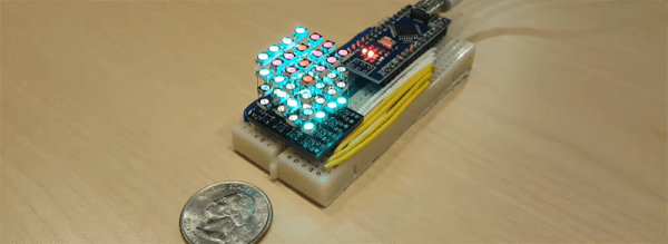
What’s the smallest RGB LED cube? A 1x1x1 cube is easy, but it’s a stupid joke and we’ve heard it before. No, to build the smallest LED cube, you’ll have to stuff 64 RGB LEDs into a cubic inch, like [Hari] did with his miniscule LED cube.

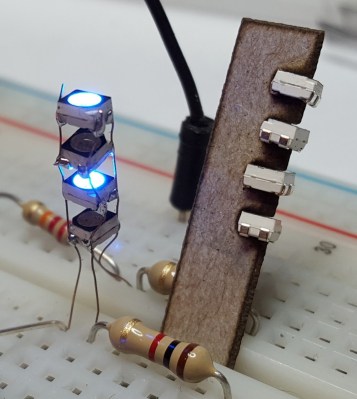
A single column of Charlieplexed LEDs. Note the resistor for scale.

One might think that individually addressable RGB LEDs are the way to go with an LED cube this small. Anything else would hide the LEDs behind a mess of wires. This isn’t the case with [Hari]’s LED cube – he’s using standard surface mount RGB LEDs for this build. But how is he connecting the things?

The entire build was inspired by the a much earlier project, the Charliecube. This LED cube, like [Hari]’s uses Charlieplexing to condense all the connections for a column of LEDs to only four wires. Repeat that sixteen times, and [Hari] built himself a tiny, one-inch cube of glowey goodness.

The cube itself was built with a PCB backplane designed in Eagle and fabbed at OSHPark. The LEDs are driven by an Arduino Nano. If you’d like to build your own, or you’re a masochist for dead bug soldering, you can grab all the design files over on [Hari]’s hackaday.io project page.

Continue reading “Building The World’s Smallest RGB LED Cube”

“You Sank My Dysprosium!”: Periodic Table Battleship

Kids these days, they have it so easy. Back in the old days, we learned our elements the hard way, by listening to “The Elements” by Tom Lehrer over and over until the vinyl wore out on the LP. Now, thanks to [Karyn], kids can learn the elements by playing “Battleship” – no tongue-twisting lyrics required.

For anyone familiar with the classic “Battleship” game, you’ll wonder why no one thought of this before. [Karyn]’s version of the game is decidedly low-tech, but gets the job done. She printed out four copies of the periodic table, added letters to label the rows, and laminated them. A pair of tables goes into a manila file folder, the tops get clipped together, and dry-erase markers are used to mark out blocks of two to five elements to represent the ships of the Elemental Navy on the lower table. Guesses at the location of the enemy ships can be made by row and series labels for the elementally challenged, or better yet by element name. Hits and misses are marked with Xs and Os on the upper table, and play proceeds until that carrier hiding in the Actinide Archipelago is finally destroyed.

This is pure genius in its simplicity and practicality, but of course there’s room for improvement. The action-packed video after the break reveals some structural problems with the file folders, so that’s an obvious version 2.0 upgrade. And you can easily see how this could be used for other tabular material – Multiplication Table Battleship? Sounds good to us. And if your nippers catch the chemistry bug from this, be sure to take a deeper dive into the structure of the periodic table with them.

Now, if you’ll excuse me: “There’s antimony, arsenic, aluminum, selenium, and hydrogen and oxygen and nitrogen and rhenium….”

Continue reading ““You Sank My Dysprosium!”: Periodic Table Battleship”

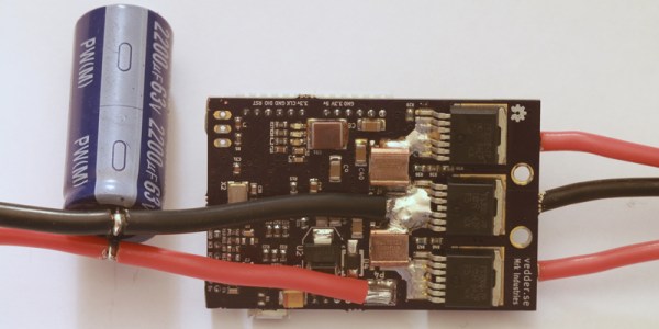
Adding Position Control To An Open Source Brushless Motor Driver

Brushless motors are everywhere now. From RC planes to CNC machines, if you need a lot of power to spin something really fast, you’re probably going to use a brushless motor. A brushless motor requires a motor controller, and for most of us, this means cheap Electronic Speed Controllers (ESC) from a warehouse in China. [Ben] had a better idea: build his own ESC. He’s been working on this project for a while, and he’s polishing the design to implement a very cool feature – position control.

We’ve seen [Ben]’s work on his custom, homebrew ESC before. It is, by any measure, a work of art. It’s capable of driving brushless and brushed motors with a powerful STM32F4 microcontroller running ChibiOS that’s able to communicate with other microcontrollers through I2C, UART, and CAN bus. If you want to build anything with a motor – from a CNC machine to an RC helicopter to an electric long board – this is the motor controller for you.

[Ben]’s latest update considers position encoders. Knowing how fast a motor is turning is very important to knowing how fast a wheel is turning, how much torque the motor is generating, and an awesome step in building the finest motor controller ever made.

Like the last update, [Ben] demonstrates the great control program written for this ESC. This GUI programs the microcontroller on the controller, with protection from high and low voltages and currents, high RPMs, duty cycle changes, and support for regenerative braking.

Thanks [Dudelbert] for sending this one in.

Continue reading “Adding Position Control To An Open Source Brushless Motor Driver”

Tinijet — Affordable Waterjet Cutting At Home

While laser cutting remains the dominant force for rapid prototyping anything made of plastic, MDF or wood, the real holy grail is the ability to cut metal — something most laser cutters are just not capable of.

In the industry, this is done using extremely high-powered laser cutters, plasma cutters, or water jet cutters. All of which are very pricey equipment for a hacker. Until now anyway. Introducing the Tinijet, the missing tool for affordable water jet cutting.

We first covered this project a few years ago when it was just a university research project called Hydro — it’s since evolved immensely, and will be available for sale very soon.

Continue reading “Tinijet — Affordable Waterjet Cutting At Home”