Fallout Inspired Cellphone Wristwatch

[Mr. Volt] mentions that some of the commenters on his videos believed that he shouldn’t be making large, retro computer themed communicator watches. He believes they are wrong, naturally we are compelled to agree with him.

thrumbz
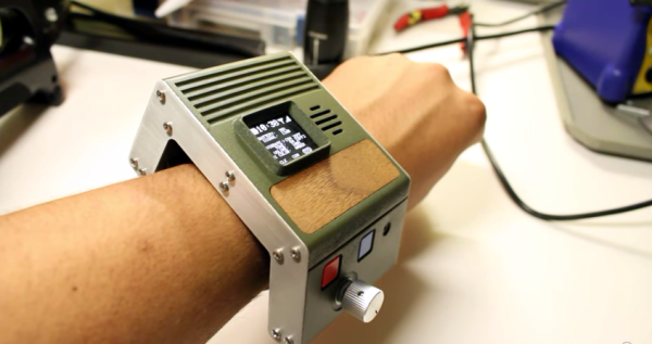
In his latest build he has produced a rather well-built and large cell-phone watch. After the untimely death of an Apple II cellphone watch, he decided to up his game and make one that could take more of a beating. The case is 3D printed, which is hard to believe given the good finish. He must have spent a long time sanding the prints. Some wood veneer for looks and aluminum panels for strength complete the assembly.

The electronics are a Teensy and a GSM module. It looks like he places calls by calling the operator since the wrist communicator only has four inputs: a red button, a blue button, and a momentary switch rotary encoder.

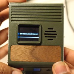
The communicator appears to work really smoothly, and it would certainly draw attention to him were he to wear it anywhere other than the Wasteland. Video after the break.

Continue reading “Fallout Inspired Cellphone Wristwatch”

Up Your CAD Game With Good Reference Photos

I’ve taken lots of reference photos for various projects. The first time, I remember suffering a lot and having to redo a model a few times before I got a picture that worked. Just like measuring parts badly, refining your reference photo skills will save you a lot of time and effort when trying to reproduce objects in CAD. Once you have a model of an object, it’s easy to design mating parts, to reproduce the original, or even for milling the original for precise alterations.

I’m adding some parts onto a cheap food dehydrator from the local import store. I’m not certain if my project will succeed, but it’s a good project to talk about taking reference photos. The object is white, indistinct, and awkward, which makes it a difficult object to take a good photo for reference use in a CAD program. I looked around for a decent tutorial on the subject, and only found one. Maybe my Google-fu wasn’t the best that day. Either way, It was mostly for taking good orthogonal shots, and not how to optimize the picture to get dimensions out of it later.

There are a few things to note when taking a reference photo. The first is the distortion and the setup of your equipment to combat it. The second is including reference scales and surfaces to assist in producing a final model from which geometry and dimensions can be accurately taken. The last is post-processing the picture to try to fight the distortion, and also to prepare it for use in cad and modeling software.

Continue reading “Up Your CAD Game With Good Reference Photos”

3D Printing Hailstone Molds For Science

Hollywood would have you believe that tornadoes are prevalent in the Midwest. We’re much more likely to see hail in the springtime—balls of slushy ice that pelt our roofs and dimple our cars. [Dr. Ian Giammanco] and his wife and fellow scientist [Tanya Brown-Giammanco] have been studying hail at the Insurance Institute for Business and Home Safety’s research lab since 2012. In 2013, their team created over 9,000 artificial hailstones and fired them at a mock-up of  a house in the first indoor full-scale hailstorm.

As fun as it sounds to shoot balls of ice at different things, they did it to better understand the humble hailstone and the damage it can do to insurable goods. Those hailstones from a few years ago were created manually by injecting molds and freezing them. Recently, [the Giammancos] and  have taken a more advanced approach to creating artificial hail so they can study the physical characteristics. They scan actual hailstones in order to create models of them. Then they make a 3D-printed mold and use it in a hail-making machine that uses diffused carbon dioxide to mimic the layering that occurs when natural hailstones are formed.

While it would be nice to be able to control hail, the next best thing is mitigating the damage it causes. The better that scientists understand hail, the better materials will become that can withstand its impact. Perhaps someone can perfect a shape-shifting building material and make it resistant to hail.

Fail Of The Week: ESP8266 Heats Temperature Sensor

[Richard Hawthorn] sent us in this interesting fail, complete with an attempted (and yet failed) clever solution. We love learning through other people’s mistakes, so we’re passing it on to you.

First the obvious-in-retrospect fail. [Richard] built a board with a temperature sensor and an ESP8266 module to report the temperature to the Interwebs. If you’ve ever put your finger on an ESP8266 module when it’s really working, you’ll know what went wrong here: the ESP8266 heated up the board and gave a high reading on the temperature sensor.

temp2
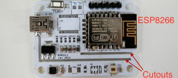
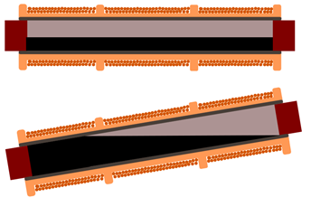
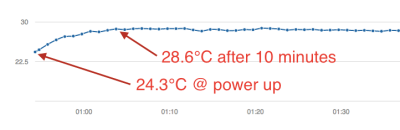
Next came the clever bit. [Richard] put cutouts into the board to hopefully stop the flow of heat from the ESP8266 module to the temperature sensor. Again, he found that the board heats up by around four degrees Celcius or nine degrees Farenheit. That’s a horrible result in any units.

What to do? [Richard’s] first ideas are to keep hammering on the thermal isolation, by maybe redoing the board again or adding a heatsink. Maybe a daughterboard for the thermal sensor? We can’t see the board design in enough detail, but we suspect that a flood ground plane may be partly to blame. Try running thin traces only to the temperature section?

[Richard]’s third suggestion is to put the ESP into sleep mode between updates to reduce waste heat and power consumption. He should be doing this anyway, in our opinion, and if it prevents scrapping the boards, so much the better. “Fix it in software!” is the hardware guy’s motto.

But we’ll put the question to you electronics-design backseat drivers loyal Hackaday readers. Have you ever noticed this effect with board-mounted temperature sensors? How did you / would you get around it?


2013-09-05-Hackaday-Fail-tips-tileFail of the Week is a Hackaday column which celebrates failure as a learning tool. Help keep the fun rolling by writing about your own failures and sending us a link to the story — or sending in links to fail write ups you find in your Internet travels.

Clever And Elegant Tilt Sensors From Ferrofluid

Let’s talk about tilt sensors for a second. The simplest tilt sensors – the dead simplest – are a few ball bearings rolling around in a small metal can. When the can is tilted, the balls roll into a pair of electrical contacts, completing the circuit. How about a drop of mercury in a glass ampule with a few contacts? Same thing. You can get more expensive tilt sensors, including a few that are basically MEMS gyros, but they’re all pretty much the same. For [Aron]’s project for the Hackaday Prize, he’s come up with a tilt sensor that is so clever, so innovative, and so elegant, we’re gobsmacked by his creativity.

5700111461442877186Instead of electrical contacts or gyroscopes, [Aron] is using induction to measure the tilt of a sensor. By wrapping a tube with one long primary winding of copper wire, and several secondary windings in various places, [Aron] built a Linear Variable Differential Transformer. If you insert an iron rod inside this transformer, different voltages will be induced in the primary. Simple, and this device is effectively a position sensor for any ferrous material.

Now for the real trick: put ferrofluid in the core of that transformer. Liquids always find their level, and different tilts will induce different voltages in the primary. Brilliant. Continue reading “Clever And Elegant Tilt Sensors From Ferrofluid”

Talk To The Glove

Two University of Washington students exercised their creativity in a maker space and created a pair of gloves that won them a $10,000 prize. Obviously, they weren’t just ordinary gloves. These gloves can sense American Sign Language (ASL) and convert it to speech.

The gloves sense hand motion and sends the data via Bluetooth to an external computer. Unlike other sign language translation systems, the gloves are convenient and portable. You can see a video of the gloves in action, below.

Continue reading “Talk To The Glove”

Don’t Take Photos Of Your Arduino 101 Either, It’s Light Sensitive

Wafer level chips are cheap and very tiny, but as [Kevin Darrah] shows, vulnerable to bright light without the protective plastic casings standard on other chip packages.

We covered a similar phenomenon when the Raspberry Pi 2 came out. A user was taking photos of his Pi to document a project. Whenever his camera flash went off, it would reset the board.

[Kevin] got a new Arduino 101 board into his lab. The board has a processor from Intel, an accelerometer, and Bluetooth Low Energy out of the box while staying within the same relative price bracket as the Atmel versions. He was admiring the board, when he noticed that one of the components glittered under the light. Curious, he pulled open the schematic for the board, and found that it was the chip that switched power between the barrel jack and the USB. Not only that, it was a wafer level package.

So, he got out his camera and a laser. Sure enough, both would cause the power to drop off for as long as the package was exposed to the strong light. The Raspberry Pi foundation later wrote about this phenomenon in more detail. They say it won’t affect normal use, but if you’re going to expose your device to high energy light, simply put it inside a case or cover the chip with tape, Sugru, or a non-conductive paint to shield it.

EDIT: [Kevin] also tested it under the sun and found conditions in which it would reset. Videos after the break.

Continue reading “Don’t Take Photos Of Your Arduino 101 Either, It’s Light Sensitive”