Analog Guts Display GPS Velocity In This Hybrid Speedometer

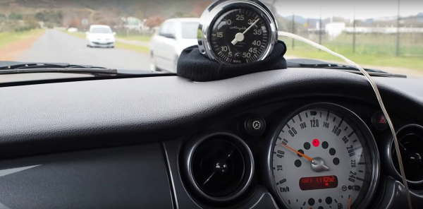
A digital dash is cool and all, but analog gauges have lasting appeal. There’s something about the simplicity of a purely mechanical gauge connected directly to a vehicle’s transmission. Of course that’s not what’s hapenning here. Instead, this build is an analog display for GPS-acquired speed data.

The video below does a good job at explaining the basics of [Grant Stephens]’ build. The display itself is a gutted marine speedometer fitted with the movement from a motorcycle tachometer. The tach was designed to take a 4-volt peak-to-peak square wave input signal, the frequency of which is proportional to engine speed. To display road speed, [Grant] stuffed an ATTiny85 with a GPS module into the gauge and cooked up a script to convert the GPS velocity data into a square wave. There’s obviously some latency, and the gauge doesn’t appear to register low speeds very well, but all in all it seems to match up well to the stock speedo once you convert to metric.

There’s plenty of room for improvement, but we can see other applications where an analog representation of GPS data could be useful. And analog gauges are just plain fun to digitize – like these old meters and gauges used to display web-scraped weather data.

Continue reading “Analog Guts Display GPS Velocity In This Hybrid Speedometer”

One Man’s Journey To Build Portable Concrete 3D Printer Produces Its First Tiny House

[Alex Le Roux] want to 3D print houses.  Rather than all the trouble we go through now, the contractor would make a foundation, set-up the 3D printer, feed it concrete, and go to lunch.

It’s by no means the first concrete printer we’ve covered, but the progress he’s made is really interesting. It also doesn’t hurt that he’s claimed to make the first livable structure in the United States. We’re not qualified to verify that statement, maybe a reader can help out, but that’s pretty cool!

The printer is a very scaled gantry system. To avoid having an extremely heavy frame, the eventual design assumes that the concrete will be pumped up to the extruder; for now he is just shoveling it into a funnel as the printer needs it. The extruder appears to be auger based, pushing concrete out of a nozzle. The gantry contains the X and Z. It rides on rails pinned to the ground which function as the Y. This is a good solution that will jive well with most of the skills that construction workers already have.

Having a look inside the controls box we can see that it’s a RAMPS board with the step and direction outputs fed into larger stepper drivers, the laptop is even running pronterface. It seems like he is generating his STLs with Sketch-Up.

[Alex] is working on version three of his printer. He’s also looking for people who would like a small house printed. We assume it’s pretty hard to test the printer after you’ve filled your yard with tiny houses. If you’d like one get in touch with him via the email on his page. His next goal is to print a fully up to code house in Michigan. We’ll certainly be following [Alex]’s tumblr to see what kind of progress he makes next!

Inside The Supplyframe Design Lab On Opening Night

Last week the Supplyframe Design Lab in Pasadena opened it’s doors, welcoming in the community to explore the newly rebuilt interior which is now filled with high-end prototyping and fabrication tools and bristling with work areas to suit any need. I had a chance to pull a few people aside during the opening night party to talk about how the Design Lab came about and what we can expect coming out of the space in the near future.

Opening night was heavily attended. I recognized many faces, but the majority of those exploring the building were new acquaintances for me. This is likely due to a strong connection the Design Lab is building with the students, faculty, and graduates of the ArtCenter College of Design. Located just down the road, it is one of the top design schools in the world.

Continue reading “Inside The Supplyframe Design Lab On Opening Night”

Reverse Engineering Quadcopter Protocols

Necessity is the mother of invention, but cheap crap from China is the mother of reverse engineering. [Michael] found a very, very cheap toy quadcopter in his local shop, and issued a challenge to himself. He would reverse engineer this quadcopter’s radio protocol. His four-post series of exploits covers finding the right frequency for the radio, figuring out the protocol, and building his own remote for this cheap toy.

[Michael] was already familiar with the capabilities of these cheap toys after reading a Hackaday post, and the 75-page, four language manual cleared a few things up for him. The ‘Quadro-Copter’ operated on 2.4GHz, but did not give any further information. [Michael] didn’t know what channel the toy was receiving on, what data rate, or what the header for the transmission was. SDR would be a good tool for figuring this out, but thanks to Travis Goodspeed, there’s a really neat trick that will put a 2.4GHz nRF24L01+ radio into promiscuous mode, allowing [Michael] to read the transmissions between the transmitter and quadcopter. This code is available on [Michael]’s github.

A needle in an electromagnetic haystack was found and [Michael] could listen in on the quadcopter commands. The next step was interpreting the ones and zeros, and with the help of a small breakout board and soldering directly to the SPI bus on the transmitter, [Michael] was able to do just that. By going through the nRF24 documentation, he was able to suss out the pairing protocol and read the stream of bytes that commanded the quadcopter.

What [Michael] was left with is a series of eight bytes sent in a continuous stream from the transmitter to the toy. These bytes contained the throttle, yaw, pitch, roll, and a ‘flip’ settings, along with three bytes of ‘counters’ that didn’t seem to do anything.  With that info in hand, [Michael] took an Arduino Nano, an nRF04L01+ transceiver, and a Wii nunchuck to build his own transmitter. If you’re looking for a ‘how to reverse engineer’ guide, it generally doesn’t get better than this.

You can check out a video of [Michael] flying his Wiimoted quadcopter below.

Continue reading “Reverse Engineering Quadcopter Protocols”

Retrotechtacular: ASCII Art In The 19th Century

Computer graphics have come a long way. Some video games today exceed what would have passed for stunning cinema animation only a few years ago. However, it hasn’t always been like this. One of the earliest forms of computer-generated graphics used text characters to draw on printers.

snoopy-calendarEarly computer rooms were likely to have a Snoopy character on green and white fan-fold paper. Calendars with some artwork were also popular (see left, and find out about the FORTRAN that created it, if you like). Ham radio operators who use teletypes (RTTY, in ham parlance) often had vast collections of punched tape that held artwork. Given that most hams in the 1950s and 1960s were men and the times were different, a lot of them were more or less “R” rated.

nixonNot all of them were, though. For example, Richard Nixon was decidedly “G” rated (see right). Simple pictures would use single characters, but sophisticated ones would use the backspace character to overprint multiple characters.

Ham Radio Art

You often hear this described as ASCII art, today, although hams usually use 5-bit BAUDOT code, so that’s a misnomer for those images, at least. Of course, today, people aren’t keen on storing roll after roll of paper tape (or even owning a tape reader) so there have been several projects to capture this art in a more modern format.

Although there is still some RTTY art activity, picture sending has been mostly replaced by slow scan TV (SSTV) which sends actual still images or other modes like FAX. Some of the newer digital modes even have the ability to send pictures. You can be discussing your radio for example, and then show the other ham a photo of the radio.

Continue reading “Retrotechtacular: ASCII Art In The 19th Century”

E Pluribus Unix, QR-Style

It’s been a long time since we’ve logged into a UNIX mainframe (other than our laptop) but one of our fond memories is the daily fortune: small, quirky, sometimes cryptic sayings that would pop up on the login screen if your system administrator had any sense of humor.

Apparently, we’re not alone. [Alastair] made his own fortune clock which gives you a new “fortune” every second instead of every login. There’s a catch, of course. It’s a QR clock — the fortune is encoded in a QR code instead of being displayed in human-readable form. You have to take a picture of the tiny OLED screen to know what it says. (Watch it sending him Shakespeare sonnets in the video below.)

You probably know QR codes are good for conveying URLs, but their use as general-purpose text containers is underappreciated in our book, so we’re glad to see this example. Now, we’ve seen QR clocks before (here, and here), and this version does have the disadvantage that you can actually tell what time it is. But we’re grateful for the trip down memory lane.

Continue reading “E Pluribus Unix, QR-Style”

Serially, Are You Syncing Or Asyncing?

I know you’ve heard of both synchronous and asynchronous communications. But do you really know the differences between the two?

Serial communication was used long before computers existed. A predecessor is the telegraph system using Morse Code, one of the first digital modes of communication. Another predecessor is the teletype, which set standards that are still used today in your Arduino or Raspberry Pi.

All you need is two wires for serial communications, which makes it simple and relatively robust. One wire is ground and the other the signal. By interrupting the power with predefined patterns, information can be transferred over both short and long distances. The challenge is receiving the patterns correctly and quickly enough to be useful.

I was a bit surprised to find out the serial port on the Arduino Uno’s ATmega328P microcontroller is a Universal Synchronous Asynchronous Transmitter Receiver (USART). I’d assumed it was only a UART (same name, just leave out synchronous) probably because my first work with serial communications was with the venerable Intel 8251 “Programmable Communication Interface”, a UART, and I didn’t expect the microcontroller to be more advanced. Silly me. Later I worked with the Zilog 8530 Serial Controller Chip, a USART, the term I’ll use for both device types.

All these devices function in the same way. You send a byte by loading it into a register and it is shifted out one bit at a time on the transmit (TX) line as pulses. The receiver accepts the pulses on a receive (RX) input and shifts them into a register, which is then read by the system. The transmitter’s job is pretty easy it just shifts out the bits at a known clock rate. The receiver’s task is more complex because it needs to know when to sample the incoming signal. How it does this is the difference between asynchronous and synchronous communications.

Continue reading “Serially, Are You Syncing Or Asyncing?”