How To Take Pictures Of PCBs

While we’ve covered light box builds and other DIY photography solutions, general picture-snapping tips and tricks are a bit out of the purview of what we normally write about. Nevertheless, [Alain] just put up a great tutorial for taking pictures of PCBs. This is a great skill to have — no one cares about what you’ve built unless you have a picture of it — and the same techniques can be applied to other small bits and bobs of electronic equipment.

As with all matters of photography, light is important. [Alain] built a DIY light box using two cheap outdoor square LED panels and some scrap wood. There’s really nothing to this build: just build a box that holds soft, diffused light.

A camera is a little more complicated than a box, and here [Alain] is using an entry-level DSLR with a kit lens. The takeaway here is to set the aperture to the highest number (or smallest hole) possible while still keeping a reasonable shutter speed. This increases the depth of field and produces a picture where the board and the tops of components are in focus.

There are a few more tips for getting the best PCB pics possible including shooting in RAW for Aperture or Lightroom, getting a macro lens, and using a tripod. Like all things, there’s a law of diminishing returns, and even with a smartphone camera and a DIY light box, you can produce some fantastic pics of PCBs.

Earth Ground And The Grid

The electrical grid transmits power over wires to our houses, and our Bryan Cockfield has covered it very well in his Electrical Grid Demystified series, but what part does the earth ground play? It’s commonly known to be used for safety, but did you know that in some cases it’s also used for power transmission?

Typical House Grounding System

Grounding system normal case

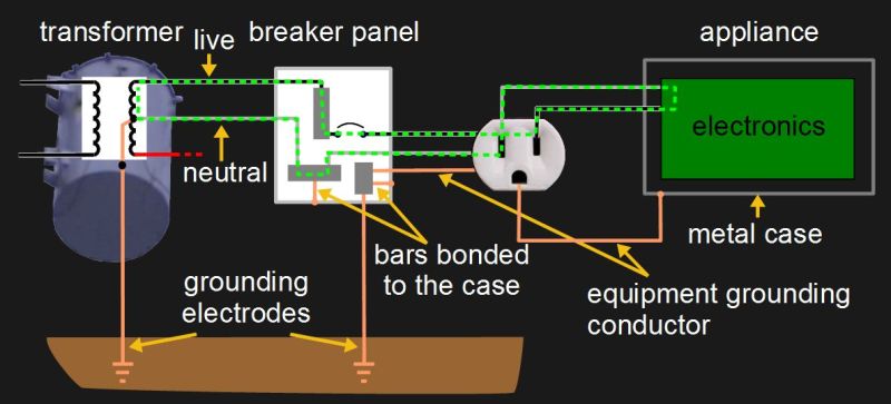
A pretty typical diagram for the grounding system for a house is shown here, along with a few of the current carrying conductors commonly called live and neutral. On the far left is the transformer outside the house and on the far right is an appliance that’s plugged in. In between them is a breaker panel and a wall socket of the style found in North America. The green dashed line shows the normal path for current to flow.

Notice the grounding electrodes for making an electrical connection with the earth ground. To use the US National Electrical Code (NEC) as an example, article 250.52 lists eight types of grounding electrodes. One very good type is an electrode encased in concrete since concrete continues to draw moisture from the ground and makes good physical contact due to its weight. Another is a grounding rod or pipe at least eight feet long and inserted deep enough into the ground. By deep enough, we mean to include factors such as the fact that the frost line doesn’t count as a good ground since it has a high resistance. You have to be careful of using metal water pipes that seemingly go into the ground, as sections of these are often replaced with non-metallic pipes during regular maintenance.

Notice also in the diagram that there are places where the various metal cases are connected to the grounding system. This is called bonding.

Now, how does all this system grounding help us? Let’s start with handling a fault.

Continue reading “Earth Ground And The Grid”

Hologram.io Offers Developers Free Cell Data

If you’ve been thinking of adding cellular connectivity to a build, here’s a way to try out a new service for free. Hologram.io has just announced a Developer Plan that will give you 1 megabyte of cellular data per month. The company also offers hardware to use with the SIM, but they bill themselves as hardware agnostic. Hologram is about providing a SIM card and the API necessary to use it with the hardware of your choice: any 2G, 3G, 4G, or LTE devices will work with the service.

At 1 MB/month it’s obvious that this is aimed at the burgeoning ranks of Internet of Things developers. If you’re sipping data from a sensor and phoning it home, this will connect you in 200 countries over about 600 networks. We tried to nail them down on exactly which networks but they didn’t take the bait. Apparently any major network in the US should be available through the plan. And they’ve assured us that since this program is aimed at developers, they’re more than happy to field your questions as to which areas you will have service for your specific application.

The catch? The first taste is always free. For additional SIM cards, you’ll have to pay their normal rates. But it’s hard to argue with one free megabyte of cell data every month.

Hologram originally started with a successful Kickstarter campaign under the name Konekt Dash but has since been rebranded while sticking to their cellular-connectivity mission. We always like getting free stuff — like the developer program announced today — but it’s also interesting to see that Hologram is keeping up with the times and has LTE networks available in their service, for which you’ll need an LTE radio of course.

The End Of Arduino 101: Intel Leaves Maker Market

This looks like the end of the road for Intel’s brief foray into the “maker market”. Reader [Chris] sent us in a tip that eventually leads to the discontinuation notice (PCN115582-00, PDF) for the Arduino 101 board. According to Intel forum post, Intel is looking for an alternative manufacturer. We’re not holding our breath.

We previously reported that Intel was discontinuing its Joule, Galileo, and Edison lines, leaving only the Arduino 101 with its Curie chip still standing. At the time, we speculated that the first wave of discontinuations were due to the chips being too fast, too power-hungry, and too expensive for hobbyists. Now that Intel is pulling the plug on the more manageable Arduino 101, the fat lady has sung: they’re giving up on hardware hackers entirely after just a two-year effort.

According to the notice, you’ve got until September 17 to stock up on Arduino 101s. Intel is freezing its Curie community, but will keep it online until 2020, and they’re not cancelling their GitHub account. Arduino software support, being free and open, will continue as long as someone’s willing to port to the platform.

Who will mourn the Arduino 101? Documentation was sub-par, but a tiny bit better than their other hacker efforts, and it wasn’t overpriced. We’re a little misty-eyed, but we’re not crying.  You?

[via Golem.de]

Duocopter Does It With Two Fewer Propellers

Quads are a great ‘copter design. The paired blades counteract each others’ torque, and varying the relative speeds of the four motors makes it easy to steer. But what if you could get by with fewer blades, substituting a significantly fancier control algorithm?

[Dirk Brunner]’s DuoCopter drone uses two propellers that counter-rotate, and it steers by increasing and decreasing the speed at which the blades rotate within a single revolution. Spinning faster on one side than the other makes it tilt. Saying this is one thing, but getting the real-time control algorithms up and running is another. From the video embedded below, it looks like [Dirk] has it working. (He also holds the world’s record for fastest quadcopter ascent, FWIW.)

Of course some of you out there won’t be satisfied until your ‘copter has only one propeller. Or maybe you’d prefer a third prop. Whatever your taste, we’re stoked to see people pushing the boundaries of copter design.

Continue reading “Duocopter Does It With Two Fewer Propellers”

Designing The Atom Smasher Guitar Pedal

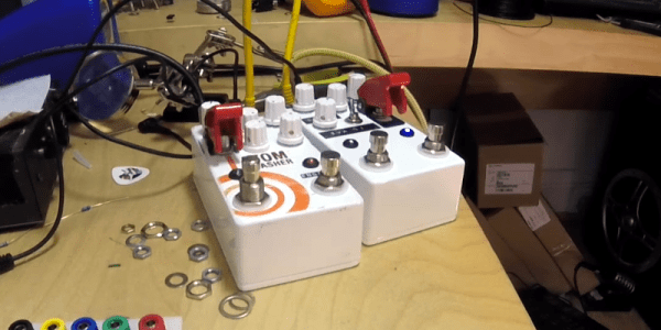
[Alex Lynham] has been creating digital guitar pedals for a while and after releasing the Atom Smasher, a glitchy lo-fi digital delay pedal, he had people start asking him how he designed digital effects pedals rather than analog effects. In fact, he had enough interest, that he wrote an article on it.

The article starts with some background on [Alex], the pedals he’s built and why he chose not to work on pedals full-time. Eventually, the article gets to the how [Alex] designed the Atom Smasher. He starts by describing the chip he used, the same one that many hobbyists, as well as commercial builders, use for delay based effects – the SpinSemi FV-1.

The FV-1 is a SMD chip used for digital delays and other effects that require a delay line – reverbs, choruses, flangers, etc. It’s programmed with an assembly-style language called SpinASM. [Alex] goes over some of the tools and references he used when designing for the pedal. He also has a list of tips for would-be effect pedal designers which work whether you’re designing digital or analogue effects.

[Alex] ends his article saying that, in the future, he might make the schematic and code available, but for the moment he’s not. The FV-1 is an interesting chip, and [Alex]’s article gives a nice high-level look at its features and how to develop for it. For some interesting guitar pedal related articles, check out this one using effects pedals to get better audio in your car, and here’s one about playing with DSP and designing a pedal with it.

Continue reading “Designing The Atom Smasher Guitar Pedal”

This Method Of Gluing Onto Curves Sucks!

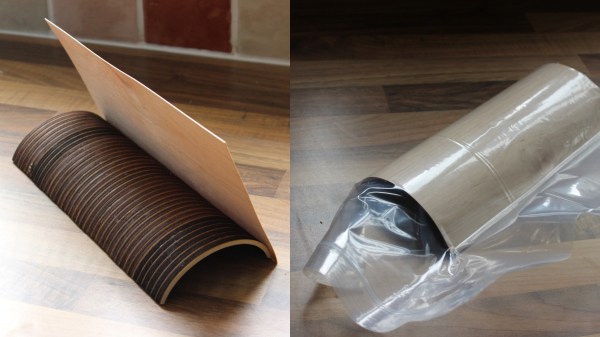
Sometimes the right tool for a job can be unusual, and this sucked only in the sense that vacuum sealing was involved. Recently [Martin Raynsford] found himself in a situation of needing to glue a wood veneer onto a curved surface, but faced a shortage of clamps. His clever solution was to vacuum-seal the whole thing and let the contour-hugging plastic bag take care of putting even pressure across the entire glued surface. After the glue had set enough to grip the materials securely, the bag was removed to let the whole thing dry completely. Gluing onto a curved surface has never been so clamp-free.

The curved piece in question was made from dozens of layers of laser-cut plywood, stacked and glued to make the curved lid of a custom-built chest. It might have been just the right shape, but it wasn’t much to look at. As you can see, giving it a wood veneer improved the appearance considerably. Wood veneers are attractive and versatile; we’ve seen for example that LEDs will shine through wood veneer quite easily.