You Can’t Build A Roland TR-808 Because You Don’t Have Faulty Transistors

That headline sounds suspect, but it is the most succinct way to explain why the Roland TR-808 drum machine has a very distinct, and difficult to replicate noise circuit. The drum machine was borne of a hack. As the Secret Life of Synthesizers explains, it was a rejected part picked up and characterized by Roland which delivers this unique auditory thumbprint.

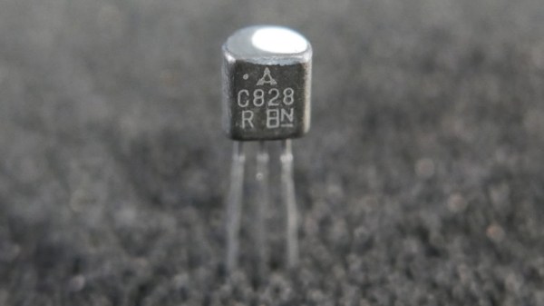
Pictured above is the 2SC828-R, and you can still get this part. But it won’t function the same as the parts found in the original 808. The little dab of paint on the top of the transistor indicates that it was a very special subset of those rejected parts (the 2SC828-RNZ). A big batch of rejects were sold to Roland back in the 1970’s — which they then thinned out in a mysterious testing process. What was left went into the noise circuit that gave the 808 its magical sizzle. When the parts ran out, production ended as newer processes didn’t produce the same superbly flawed parts.

This is an incredible story that was highlighted in 808, a documentary premiered at SXSW back in 2015. The film is currently streaming on Amazon Prime (and to rent everywhere else) and is certainly worth your time just to grasp how seminal this drum machine has been in hip hop and several other music genres.

For modern product developers, betting your production on a batch of reject parts is just batty. But it was a very different time with a lot fewer components on the market. What worked, worked. You do have to wonder how you stumble upon the correct trait in an obscure batch of reject parts? Looks like we’ll be adding Ikutar Kakehashi’s book I Believe in Music: Life Experiences and Thoughts on the Future of Electronic Music by the Founder of the Roland Corporation to our reading list.

[via EMSL]

ESP8266 Powered Tank With Voice Control

The high availability of (relatively) low cost modular components has made building hardware easier than ever. Depending on what you want to do, the hardware side of a project might be the hacker equivalent of building with LEGO. In fact, we wouldn’t be surprised if it literally involved building with LEGO. In any event, easy and quick hardware builds leave more time for developing creative software to run the show. The end result is that we’re starting to see very complex systems broken down into easy-to-replicate DIY builds that would have been nearly impossible just a few years ago.

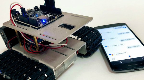
[igorfonseca83] writes in to share with us his modular tank platform that uses the ESP8266 and a handful of software hacks to allow for voice control from the user’s mobile device. Presented as a step-by-step guide on Hackaday.io, this project is perfect for getting started in Internet-controlled robotics. Whether you just want to experiment with Google Assistant integration or use this as a blank slate to bootstrap a remotely controlled rover, this project has a lot to offer.

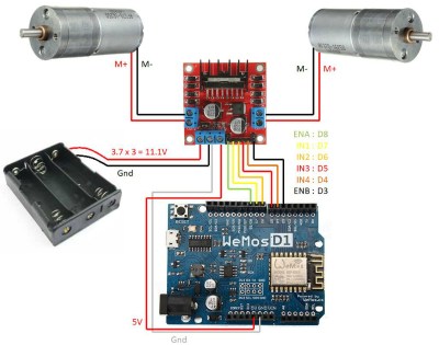
The chassis itself is a commercially available kit, and [igorfonseca83] uses a L298N dual channel H-bridge module to control its two geared motors. A Wemos D1 serves as the brains of the operation, and three 18650 3.7V batteries provide the juice to keep everything running. There’s plenty of expansion capability to add sensors and other gear, but for this project getting it rolling was the only concern.

Software wise, there are a number of pieces that work together to provide the Google Assistant control demonstrated in the video after the break. It starts by interfacing the ESP8266 board Adafruit.IO, which connects to IFTTT, and then finally Google Assistant. By setting up a few two variable phrases in IFTTT that get triggered by voice commands in Google Assistant, you can push commands back down to the ESP8266 through Adafruit.IO. It’s a somewhat convoluted setup, admittedly, but the fact that involves very little programming makes it an interesting solution for anyone who doesn’t want to get bogged down with all the minutiae of developing your own Internet control stack.

[igorfonseca83] is no stranger to building remotely controlled rovers. Last year we covered another of his creations which was commanded through a web browser and carried an Android phone to stream video of its adventures.

Continue reading “ESP8266 Powered Tank With Voice Control”

Save Fingers, Save Lives With A No-Voltage Release For The Shop

Imagine the scenario: you’re spending some quality time in the shop with your daughter, teaching her the basics while trying to get some actual work done. You’re ripping some stock on your cheap table saw when your padiwan accidentally hooks the power cord with her foot and pulls out the plug. You have a brief chat about shop safety and ask her to plug it back in. She stoops to pick up the cord and plugs it back in while her hand is on the table! Before you can stop the unfolding tragedy, the saw roars to life, scaring the hell out of everyone but thankfully doing no damage.

If that seems strangely specific it’s because it really happened, and my daughter was scared out of the shop for months by it. I’ll leave it to your imagination what was scared out of me by the event. Had I only known about no-voltage release switches, or NVRs, I might have been able to avoid that near-tragedy. [Gosforth Handyman] has a video explaining NVRs that’s worth watching by anyone who plugs in anything that can spin, cut, slice, dice, and potentially mutilate. NVRs, sometimes also called magnetic contactors, do exactly what the name implies: they switch a supply current on and off, but automatically switch to an open condition if the supply voltage fails.

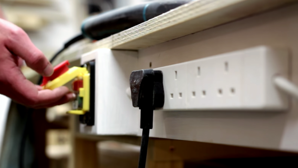
Big power tools like table saws and mills should have them built in to prevent a dangerous restart condition if the supply drops, but little tools like routers and drills can still do a lot of damage if they power back up while switched on. [Gosforth] built a fail-safe power strip for his shop from a commercial NVR, and I’d say it’s a great idea that’s worth considering. Amazon has a variety of NVRs that don’t cost much, at least compared to the cost of losing a hand.

True, an NVR power strip wouldn’t have helped me with that cheap table saw of yore, but it’s still a good idea to put some NVR circuits in your shop. Trust me, it only takes a second’s inattention to turn a fun day in the shop into a well-deserved dressing down by an angry mother. Or worse.

Continue reading “Save Fingers, Save Lives With A No-Voltage Release For The Shop”

Transistor Logic Clock Gets Stacked Up

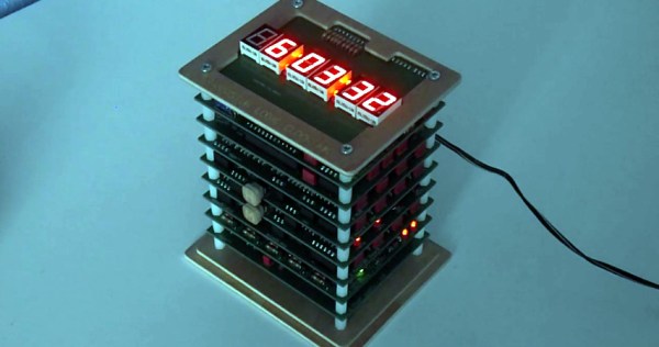
A couple years back we covered a very impressive transistor logic clock which was laid out so an observer could watch all of the counters doing their thing, complete with gratuitous blinkenlights. It had 777 transistors on 41 perfboards, and exactly zero crystals: the clock signal was extracted from the mains frequency of 50 Hz. It was obviously a labor of love and certainly looked impressive, but it wasn’t exactly the most practical timepiece we’d ever seen.

Creator [B Brett] recently wrote in to share news that the second version of his transistor logic clock has been completed, and we can confidently say it’s a triumph. He’s dropped the 41 perfboards in favor of 9 professionally fabricated PCBs, which this time around are stacked vertically to make it a bit more desktop friendly. The end goal of a transistor logic clock that you can take apart to study is the same, but this “MkII” as he calls it is a far more refined version of the concept.

In addition to using fewer boards, the new MkII design cuts the logic down to only 283 transistors. This is thanks in part to the fact that he allowed himself the luxury of including an oscillator this time. The clock uses a standard watch crystal at 32.768 KHz, the output of which is converted into a square wave through a Schmitt trigger. This is then fed into a divider higher up the stack which uses flip flops to produce 1Hz and 2Hz signals for use throughout the rest of the clock.

In addition to the original version of this project, we’ve also seen a beautiful single-board wall mounted version, and even a “dead bug” style one built from scraps.

Continue reading “Transistor Logic Clock Gets Stacked Up”

Count To F Easily With This DIY Calculator

Some of the greatest electronic calculators of all time, including the venerable HP-16C, included functionality to convert numbers between different bases. 3735928559 might not mean much in base 10, but convert that to hex, and you’ll offend vegetarians. If the great calculators of yore had a way to convert between number bases, that means someone must make a standalone device to do the same, right? That’s what [leumasyerrp] is doing for their entry into the Hackaday Prize, anyway.

The Base Convert project is a simple desktop calculator designed to convert between hexadecimal, decimal, and binary. To do this, there’s an 8×8 key matrix for the numbers 0 through F. There are sixteen single LEDs, four seven-segment LEDs for the hex display, and six seven-segment LEDs for the decimal display.

While this is really just a project [leumasyerrp] came up with to learn the MSP430 microcontroller, this looks like a fantastic project given it’s great use of milled PCB for a front panel, careful selection of standoff height, and everything is tucked away into a package that looks about as professional as you can expect from a device made entirely from PCBs. Of course, the Base Convert calculator works as expected, and can easily change between number bases.

Sometimes it’s not about building the hardest or most complex project, but instead simply putting the most amount of polish into a simple project. This is a project that does that well, and we’re happy to have this in the running for the Hackaday Prize.

How To Add UART To Your FPGA Projects

Being able to communicate between a host computer and a project is often a key requirement, and for FPGA projects that is easily done by adding a submodule like a UART. A Universal Asynchronous Receiver-Transmitter is the hardware that facilitates communications with a serial port, so you can send commands from a computer and get messages in return.

Last week I wrote about an example POV project that’s a good example for learn. It was both non-trivial and used the board’s features nicely. But it has the message hard coded into the Verilog which means you need to rebuild the FPGA every time you want to change it. Adding a UART will allow us to update that message.

The good news is the demo is open source, so I forked it on GitHub so you can follow along with my new demo. To illustrate how you can add a UART to this project I made this simple plan:

Continue reading “How To Add UART To Your FPGA Projects”

One Square Inch Expanded In The Time Dimension

No, we’re not talking about spooky feats of General Relativity. But you should know that the Return of the Square Inch Project just got its deadline extended.

If you missed the call the first time around, our favorite user-contributed contest on Hackaday.io is up and running again. Hackaday.io tossed in some good money for prizes, and folks started thinking about what functionality they could cram inside a 25.4 mm x 25.4 mm square. But while one constraint can help bring out creativity, adding a tight deadline to a tight squeeze caused a number of our entrants to ask for an extension.

If you’re working on the Square Inch Project, you’ve got until October 1st to get your boards ready. Breathe a quick sigh of relief and then get back to soldering! We’re looking forward to seeing all the great entries.