This Boxing Bell Is A Trip

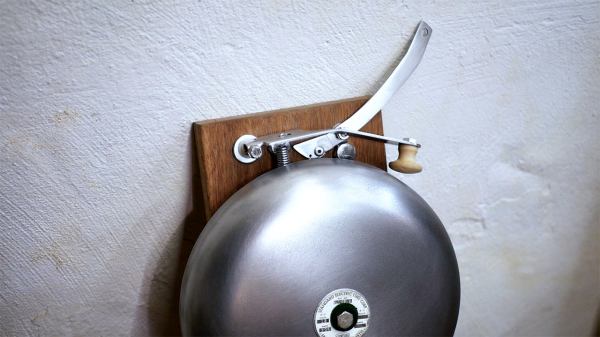
[MeasuredWorkshop] wanted to know how a boxing bell mechanism worked. The best way to learn is by doing, so he jumped right in and built one! Boxing bells are a rare surviving example of the trip bell mechanism. Trip bells were used in schools and public buildings as fire alarms. They’ve since been replaced by modern electric systems.

The mechanical linkage behind the trip bell is a one-way lever. This is the arm you pull on. It has a hinged section which stays rigid when the arm is pulled down, but rotates away when the arm is released. [Measured Workshop] built the mechanics of his bell using rather basic tools. The brunt of the work was handled by an angle grinder and a drill press.

The sounder for this boxing bell came from an old school bell. The industrial grey paint was chemically stripped, and the metal cleaned up for a nice brushed finish. The metal stands out nicely against the wood board [Measured Workshop] used as a base.

The finished product looks and sounds the part – now he just has to find a boxing gym in need of a bell!

We’re really becoming fond of the “wordless workshop” style videos that have been popping up on YouTube. [Jimmy DiResta] has been doing it for years, and relative newcomers [HandToolRescue] and [Measured Workshop] are both producing some great content!

Continue reading “This Boxing Bell Is A Trip”

Catching The (PCIe) Bus

If you are trying to learn about FPGAs, there is only so far you can go with the usual blinking lights and VGA outputs. Eventually, you want to do something more. Although not terribly cheap, you can get FPGA boards in a PCIe form-factor and use them directly with PC software. Is it easy? Well, it isn’t flashing an LED, but there are tools to help. [Angelos Kyriakos] did a Master’s thesis on the very subject and used a project known as RIFFA to help with the task.

RIFFA (Reusable Integration Framework for FPGA Accelerators) is a simple framework for communicating data from a host CPU to an FPGA via a PCI Express bus. The framework requires a PCIe enabled workstation and an FPGA on a board with a PCIe connector. RIFFA supports Windows and Linux, Altera and Xilinx, with bindings for C/C++, Python, MATLAB, and Java. With proper design, RIFFA can transfer quite a bit of data in a short period of time between your computer and your FPGA.

Continue reading “Catching The (PCIe) Bus”

Resurrecting An Amiga CD32

As an editor on Amiga magazines in a previous life, this is kind of bittersweet. [RetroManCave] was donated an Amiga CD32 games system, and it is trying to resurrect it. If you’ve not heard of it, the CD32 was a 1993 games console based on the Amiga home computer system. It was the last gasp for Commodore, the beleaguered company behind the Amiga. In this first video of a series, they take the system apart, take you through what’s inside and boot it up. The system boots, but there is some sort of problem with the video sync, and they will be taking a closer look at fixing that next. We have featured a couple of similar projects from [RetroManCave] before, such as their brain transplant on a Big Trak toy and Commodore 64 fix. This video (after the break) is worth a watch if you are curious about old systems like this, want some tips on resurrecting old hardware or just want to shed a tear as your misspent youth is torn apart before your eyes.

Continue reading “Resurrecting An Amiga CD32”

Underwater Logging For Science

Logging data with an Arduino is old-hat for most Hackaday readers. However, [Patricia Beddows] and [Edward Mallon] had some pretty daunting requirements. Their sensors were going underground and underwater as part of an effort to study conditions underwater and in caves. They needed to be accessible, yet rugged. They didn’t want to use batteries that would be difficult to take on airplanes, but also wanted more than a year of run time. You can buy all that, of course, if you are willing to pay the price.

Instead, they used off-the-shelf Arduino boards connected together inside PVC housings. Three alkaline AA batteries are compact and give them more than a year of run time. They wrote a journal paper to help other scientists use the same techniques for the Sensors journal published by the Multidisciplinary Digital Publishing Institute.

Continue reading “Underwater Logging For Science”

Analyzing Hobby Motors With An Oscilloscope

We always like finding new excuses reasons to use our test equipment, so we couldn’t help but be intrigued by this tip from [Joe Mosfet]. He uses the ever-popular Rigol DS1054Z to demonstrate the differences between a handful of brushless motors when rotated by his handheld drill at a constant RPM. Not only is he able to identify a blown motor, but it allows him to visualize their specifications which can otherwise seem a bit mystifying.

One wire from each motor is used as the ground, and channels one and two are connected to the remaining wires. Despite the DS1054Z having four channels, [Joe] is actually only using two of them here. The third channel being displayed is a virtual channel created by a math function on the scope.

After wiring them up, each motor got put into the chuck of his drill and spun up to 1430 RPM. The resulting waveforms were captured, and [Joe] walks us through each one explaining what we’re seeing on the scope.

The bad motor is easy to identify: the phases are out of alignment and in general the output looks erratic. Between the good motors, the higher the Kv rating of the motor, the lower voltage is seen on the scope. That’s because Kv in the context of brushless motors is a measurement of how fast the motor will spin for each volt. The inverse is also true, and [Joe] explains that if he could spin his 2450Kv motor at exactly 2450 RPM, we should see one volt output.

Beyond demonstrating the practical side of Kv ratings, [Joe] also theorizes that the shape of the wave might offer a glimpse into the quality of the motor’s construction. He notes his higher end motors generate a nice clean sine wave, while his cheaper ones show distortion at the peaks. An interesting note, though he does stress he can’t confirm there’s a real-world performance impact.

Last year we featured a similar method for identifying bad brushless motors using a drill press and an oscilloscope, but we liked that [Joe] went through the trouble of testing multiple motors and explaining the differences in their output.

[via /r/multicopter]

How To Control The Lights With A TV Remote

In this day and age of the Internet of Things and controlling appliances over the internet, the idea of using an old-fashioned television remote to do anything feels distinctly 2005. That doesn’t mean it’s not a valid way to control the lights at home, and [Atakan] is here to show us how it’s done.

To the experienced electronics maker, this is yesterday’s jam, but [Atakan] goes to great lengths to hash out the whole process from start to finish, from building the circuitry to switch the lights through to the code necessary to make a PIC do your bidding. It’s rare to see such a project done with a non-Arduino platform, but rest assured, such things do exist. There’s even some SPICE simulation thrown in for good measure, if you really want to get down to the nitty-gritty.

Perhaps the only thing missing from the writeup is a primer on how to execute the project safely, given that it’s used with a direct connection to live mains wiring. We’d love to hear in the comments about any changes or modifications that would be necessary to ensure this project doesn’t hurt anyone or burn an apartment complex down. Sometimes you can switch lights without a direct connection to the mains, however – like this project that interfaces mechanically with a standard light switch.

Repairs You Can Print: Better Cable Splicing With 3D Printed Parts

A while back, [Marius] was faced with a problem. A friend of his lives in the middle of a rainforest, and a microphone was attacked by a dirty, greasy rat. The cable was gnawed in half, and with it went a vital means of communication with the outside world. The usual way of fixing a five- or six-conductor cable is with heat shrink, lineman’s splices, insulating tape, and luck. [Marius] needed something better than that, so he turned to his 3D printer and crafted his own wire splice enclosure.

The microphone in question is a fancy Jenal jobbie with a half-dozen or so conductors in the cable. A junction box was the obvious solution to this problem, and a few prototypes, ranging from rectangular to fancy oval boxes embossed with a logo were spat out on a 3D printer. These junction boxes have holes on either end, and when the cable ends are threaded through these holes, the wires can be spliced, soldered, and insulated from each other.

This microphone had to hold up to the rigors of the rainforest and rats, so [Marius] had to include some provisions for waterproofing. This came in the form of a hot glue gun; just fill the junction box with melted hot glue, pop the cover on, and just wait for it to cool. Like all good repairs, it works, and by the time this repair finally gives out, something else in the microphone is sure to go bad.

It’s a great repair, and an excellent example of how a 3D printer can make repairs easy, simple, cheap, and almost as good as the stock part. You can check out a few videos of the repair below.

Continue reading “Repairs You Can Print: Better Cable Splicing With 3D Printed Parts”