Dashing Diademata Delivers Second Generation ROS

A simple robot that performs line-following or obstacle avoidance can fit all of its logic inside a single Arduino sketch. But as a robot’s autonomy increases, its corresponding software gets complicated very quickly. It won’t be long before diagnostic monitoring and logging comes in handy, or the desire to encapsulate feature areas and orchestrate how they work together. This is where tools like the Robot Operating System (ROS) come in, so we don’t have to keep reinventing these same wheels. And Open Robotics just released ROS 2 Dashing Diademata for all of us to use.

ROS is an open source project that’s been underway since 2007 and updated regularly, each named after a turtle species. What makes this one worthy of extra attention? Dashing marks the first longer term support (LTS) release of ROS 2, a refreshed second generation of ROS. All high level concepts stayed the same, meaning almost everything in our ROS orientation guide is still applicable in ROS 2. But there were big changes under the hood reflecting technical advances over the past decade.

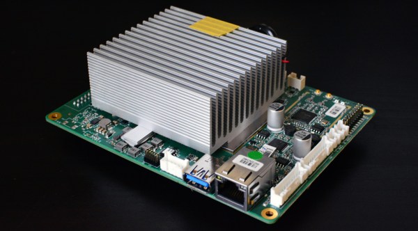
ROS was built in an age where a Unix workstation cost thousands of dollars, XML was going to be how we communicate all data online, and an autonomous robot cost more than a high-end luxury car. Now we have $35 Raspberry Pi running Linux, XML has fallen out of favor due to processing overhead, and some autonomous robots are high-end luxury cars. For these and many other reasons, the people of Open Robotics decided it was time to make a clean break from legacy code.

The break has its detractors, as it meant leaving behind the vast library of freely available robot intelligence modules released by researchers over the years. Popular ones were (or will be) ported to ROS 2, and there is a translation bridge sufficient to work with some, but the rest will be left behind. However, this update also resolved many of the deal-breakers preventing adoption outside of research, making ROS more attractive for commercial investment which should bring more robots mainstream.

Judging by responses to the release announcement, there are plenty of people eager to put ROS 2 to work, but it is not the only freshly baked robotics framework around. We just saw Nvidia release their Isaac Robot Engine tailored to make the most of their Jetson hardware.

The Atomic Pi: Is It Worth It?

Several months ago, a strange Kickstarter project from ‘Team IoT’ appeared that seemed too good to be true. The Atomic Pi was billed as a high-power alternative to the Raspberry Pi, and the specs are amazing. For thirty five American buckaroos, you get a single board computer with an Intel processor. You get 16 Gigs of eMMC Flash, more than enough for a basic Linux system and even a cut-down version of Windows 10. You have WiFi, you have Bluetooth, you have a real time clock, something so many of the other single board computers forget. The best part? It’s only thirty five dollars.

Naturally, people lost their minds. There are many challengers to the Raspberry Pi, but nothing so far can beat the Pi on both price and performance. Could the Atomic Pi be the single board computer that finally brings the folks from Cambridge to their knees? Is this the computer that will revolutionize STEM education, get on a postage stamp, and sell tens of millions of units?

No. The answer is no. While I’m not allowed to call the Atomic Pi “literal garbage” because our editors insist on the technicality that it’s “surplus” because they were purchased before they hit the trash cans, there will be no community built around this thirty five dollar single board computer. This is a piece of electronic flotsam that will go down in history right next to the Ouya console. There will be no new Atomic Pis made, and I highly doubt there will ever be any software updates. Come throw your money away on silicon, fiberglass and metal detritus! Or maybe you have a use for this thing. Meet the Atomic Pi!

Continue reading “The Atomic Pi: Is It Worth It?”

Assessing Nozzle Wear In 3D-Printers

How worn are your nozzles? It’s a legitimate question, so [Stefan] set out to find out just how bad 3D-printer nozzle wear can get. The answer, as always, is “It depends,” but exploring the issue turns out to be an interesting trip.

Reasoning that the best place to start is knowing what nozzle wear looks like, [Stefan] began by printing a series of Benchies with brand-new brass nozzles of increasing diameter, to simulate wear. He found that stringing artifacts, interlayer holes, and softening of overhanging edges and details all worsened with increasing nozzle size. Armed with this information, [Stefan] began a torture test of some cheap nozzles with both carbon-fiber filament and a glow-in-the-dark filament, both of which have been reported as nozzle eaters. [Stefan] found that to be the case for at least the carbon-fiber filament, which wore the nozzle to a nub after extruding only 360 grams of material.

Finally, [Stefan] did some destructive testing by cutting used nozzles in half on the mill and looking at them in cross-section. The wear on the nozzle used for carbon-fiber is dramatic, as is the difference between brand-new cheap nozzles and the high-quality parts. Check out the video below and please sound off in the comments if you know how that peculiar spiral profile was machined into the cheap nozzles.

Hats off to [Stefan] for taking the time to explore nozzle wear and sharing his results. He certainly has an eye for analysis; we’ve covered his technique for breaking down 3D-printing costs in [Donald Papp]’s  “Life on Contract” series.

Continue reading “Assessing Nozzle Wear In 3D-Printers”

Infineon Buys Cypress For $10B

Infineon will acquire Cypress Semiconductors for nearly $10 Billion dollars. This is the latest merger or acquisition in the semiconductor industry, and these mergers and acquisitions show no sign of stopping anytime soon.

Infineon’s market currently consists mostly of products aimed at the automotive market and power management and control. Cypress, likewise, has a wide portfolio of automotive electronics, from the guts of instrument clusters to the brains of infotainment systems. The automotive electronics industry is going gangbusters right now, and companies in the market are flush with cash; Infineon acquiring Cypress allows both companies to focus their R&D to develop products for the same market.

As with all mergers and acquisitions, there is the question of what may be lost, or what may go out of production. Cypress is most famous for their PSOC microcontrollers, but for now those uCs, and their CapSense capability, seem safe. Cypress is also noteworthy for manufacturing old-school memories, but again it looks like you’ll still be able to buy these years down the line; in any event, Alliance memory is still around stuffing DRAMs in DIPs.

This acquisition of Cypress by Infineon is one of the largest in recent memory. Apple recently bought a $600 Million stake in Dialog, and Microchip acquired Microsemi for $8.35 Billion. Tesla bought Maxwell Technologies for a mere $218 Million. This deal between Infineon and Cypress puts the company in the upper echelon of recent mergers and acquisitions.

You Don’t Need That Bulky CRT Oscilloscope Anymore

While it might be nice to use a $4,000 oscilloscope in a lab at a university or well-funded corporate environment, a good portion of us won’t have access to that kind of equipment in our own home shops. There are a few ways of getting a working oscilloscope without breaking the bank, though. One option is to find old CRT-based unit for maybe $50 on craigslist which might still have 60% of its original 1970s-era equipment still operational. A more reliable, and similarly-priced, way of getting an oscilloscope is to just convert a device you already have.

The EspoTek Labrador is an open-source way of converting a Raspberry Pi, Android device, or even a regular run-of-the-mill computer into a working oscilloscope. It’s a small USB device with about a two square inch PCB footprint that includes some other features as well like a signal generator and logic analyzer. It’s based on an ATxmega which is your standard Arduino-style AVR microcontroller but geared for low power usage. It looks as though it is pretty simple to use as well, and the only requirements are that you can install the software needed for the device on whatever computing platform you decide to use.

While the Labrador is available for sale at their website, it is definitely a bonus when companies offer products like this but also release the hardware and software as open source. That’s certainly a good way to get our attention, at least. You can build your own if you’d like, but if you’d rather save the time you have pre-built options. And it doesn’t hurt that most of the reviews of this product seem to be very favorable (although we haven’t tried one out ourselves). If you’d prefer an option without a company backing it, though, we have you covered there too.

Storm Chasers Score Bullseye On Tornado With Instrument-Packed Rocket

Model rockets are a heck of a lot of fun, and not a few careers in science and engineering were jump-started by the thrilling woosh and rotten-egg stench of an Estes rocket launch. Adding simple instrumentation to the rocket doubles the fun by allowing telemetry to be sent back, or perhaps aiding in recovery of a lost rocket. Sending an instrument-laden rocket into a tornado is quite a few notches past either of those scenarios, and makes them look downright boring by comparison.

A first and hopefully obvious point: just don’t do this. [ChasinSpin] and [ReedTimmer] are experienced storm chasers, and have a small fleet of purpose-built armored vehicles at their disposal. One such vehicle, the Dominator, served as a mobile launch pad for their rocket as they along with [Sean Schofer] and [Aaron Jayjack] chased what developed into an EF4 monster tornado near Lawrence, Kansas on May 28. They managed to score a direct hit on the developing tornado, only 100 feet (30 meters) away at the time, and which took the rocket to 35,000 ft (10.6 km) and dragged it almost 30 miles (42 km) downrange. They lost touch with it but miraculously recovered it from a church parking lot.

They don’t offer a lot of detail on the rocket itself, but honestly it looks pretty much off-the-shelf, albeit launched from an aimable launchpad. [ChasinSpin] does offer a few details on the instrument package, though – a custom PCB with GPS, IMU, a temperature/humidity/barometric pressure sensor, and a LoRa link to send a data packet back every second. The card also supported an SD card for high-resolution measurements at 10 times per second. Check out the launch in the video below, and be sure to mouse around to get a look at the chaotic environment they were working in.

Even if this isn’t as cool as sending a sounding rocket into an aurora, it’s still really cool. We’re looking forward to seeing what kind of data this experiment collected, and what it reveals about the inner workings of these powerful storms.

Continue reading “Storm Chasers Score Bullseye On Tornado With Instrument-Packed Rocket”

Solder SMDs With A Pan O’ Sand

For those that grew up working with through-hole components, surface mount parts can be challenging to deal with. However, there are plenty of techniques out there that are more than accessible to the DIY set. With the right gear, soldering SMD boards is a snap – just get yourself a hot pan of sand (Youtube link, embedded below)!

The process starts with a professionally manufactured PCB, and accompanying stencil. All major PCB CAD packages are capable of generating stencil files these days, and many manufacturers will throw in a laser cut stencil for minimal extra cost with a PCB order. The board is first mounted on a stable surface, and has solder paste applied, before components are placed with tweezers. Perfect placement isn’t necessary, as the surface tension of the molten solder pulls components into their correct orientations. The populated board is then placed on a bed of sand in a frying pan, which is placed on an induction cooktop. The board is then heated until the solder melts, and all the components are neatly reflowed. Once allowed to cool, the board is done!

The trick is that the sand helps evenly heat the circuit board, while keeping it a safe distance away from the heat source. Results are good, and the process is far quicker than hand soldering. It’s easy to keep an eye on the process too. Of course, the traditional method is still to use the humble toaster oven, but new techniques are always useful. We’ve seen it done with a Bunsen burner, too. Video after the break.

Continue reading “Solder SMDs With A Pan O’ Sand”