If you’ve ever pushed the needle a bit on your Raspberry Pi, there’s a good chance you’ve been visited by the dreaded lightning bolt icon. When it pops up on the corner of the screen, it’s a warning that the input voltage is dipping into the danger zone. If you see this symbol often, the usual recommendation is to get a higher capacity power supply. But experienced Pi wranglers will know that the board can still be skittish.
Sick of seeing this icon during his MAME sessions, [Majenko] decided to attack the problem directly by taking a close look at the power supply circuitry of the Pi 4. While the official schematics for everyone’s favorite single-board computer are unfortunately incomplete, he was still able to identify a few components that struck him as a bit odd. While we wouldn’t necessarily recommend you rush out and make these same modifications to your own board, the early results are certainly promising.
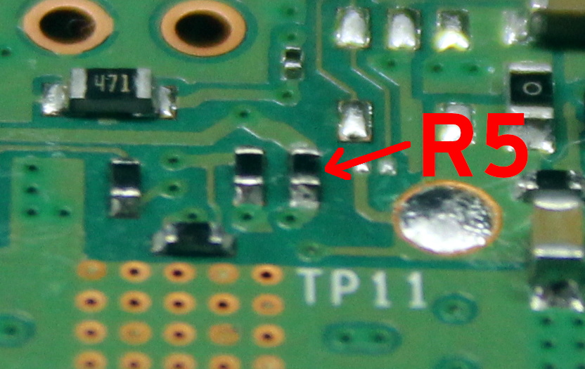
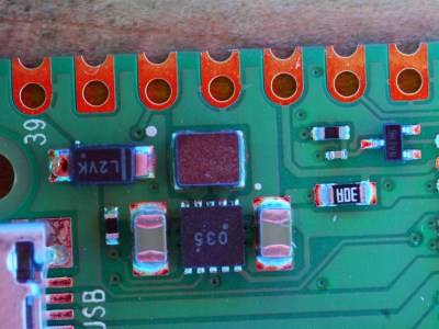
The first potential culprit [Majenko] found was a 10 ohm resistor on the 5 V line. He figured this part alone would have a greater impact on the system voltage than a dodgy USB cable would. The components aren’t labeled on the Pi’s PCB, but with a little poking of the multimeter he was able to track down the 0402 component and replace it with a tiny piece of wire. He powered up the Pi and ran a few games to test the fix, and while he definitely got fewer low-voltage warnings, there was still the occasional brownout.
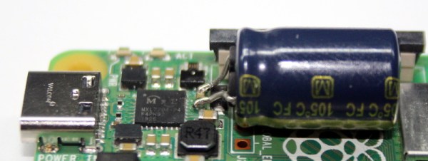
Going back to the schematic, he noticed there was a 10 uF capacitor on the same line as the resistor. What if he bumped that up a bit? The USB specifications say that’s the maximum capacitive load for a downstream device, but he reasoned that’s really only a problem for people trying to power the Pi from their computer’s USB port.
Tacking a 470 uF electrolytic capacitor to the existing SMD part might look a little funny, but after the installation, [Majenko] reports there hasn’t been a single low-voltage warning. He wonders if the addition of the larger capacitor might make removing the resistor unnecessary, but since he doesn’t want to mess with a good thing, that determination will be left as an exercise for the reader.
It’s no secret that the Raspberry Pi 4 has been plagued with power issues since release, but a newer board revision released last year helped smooth things out a bit. While most people wouldn’t go this far just to address the occasional edge case, it’s good to know folks are out there experimenting with potential fixes and improvements.
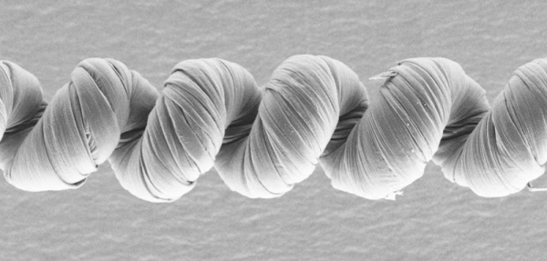
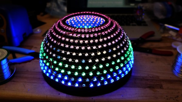
 The principle behind this tool is as unexpected and simple as it is clever; by having different colours of light from different elevations of the dome it ensures that each different angle of the solder joint surface reflects a different colour. Thus a colour photograph shot from directly above the board allows visual inspection of the quality of the solder joints by the rainbow of colours that appears around their edges. This process can even be automated with OpenCV or similar, hence the process is referred to as Automated Optical Inspection, or AOI.