Dissecting The AVR DebugWire

Anyone who’s ever written more than a dozen or so lines of code knows that debugging is a part of life in our world. Anyone who’s written code for microcontrollers knows that physical debugging is a part of our life as well. Atmel processors use a serial communications protocol called debugWire, which is a simpler version of JTAG and allows full read/write access to all registers and allows one to single step, break, etc. [Nerd Ralph], a prominent fixture here at Hackaday has dug into the AVR debugWire protocol and enlightened us with some valuable information.

While the protocol side of debugWire is a mostly-solved problem, the physical layer was giving him trouble. He started with a diode, and then went through a couple resistors and other components to interface with the debugWire pin on the AVR microcontroller, doing most of the troubleshooting work so now you don’t have to. He notes that interface components might need to be tailored to specific USB-TTL adapters, so keep that in mind if you care to delve into working with debugWire yourself.

We’re no strangers to debugging techniques here at Hackaday. As always, be sure to let us know if you run across any new techniques or try anything new yourself!

Reverse-Engineering DebugWire

Has this ever happened to you? You start out on a reverse-engineering project, start digging in, and then get stumped. Then you go looking on the Internet for help, and stumble across someone who’s already done exactly what you’re trying to do?

[Geekabit] wrote us with a version of this tale of woe. In his case, the protocol to be reversed was Atmel’s debugWire protocol for debugging on low-pin-count parts. There are a number of websites claiming it’s “secret” or whatever, but it actually looks like it’s just poorly documented. Anyway, [RikusW] seems to have captured all of the signals way back in 2011. Good job!

The best part of [geekabit]’s story is that he had created the Wikipedia page on debugWire himself to inspire collaboration on reverse-engineering the protocol, and someone linked in [RiskusW]’s work. When [geekabit] picked up the problem again a bit later, he did a bit of web research and found it solved — on the page that he started.

Maybe it’s not a tale of woe after all, but a tale of unintentional collaboration. Anyway, it serves as a reminder that if you’re interested in the destination more than the voyage of discovery, it never hurts to do your research beforehand. And now we all know about the low-level details of the debugWire protocol. Anyone written up a driver yet?

Thanks [geekabit] for the tip and the story! Image from ATmega32-AVR, which explains nicely how to use the Dragon in debugWire mode.

A render of the USB Blaster, showing all the major parts

The Cheapest USB Blaster Ever, Thanks To CH552

Here’s a CH552G-based USB Blaster project from [nickchen] in case you needed more CH552G in your life, which you absolutely do. It gives you the expected IDC-10 header ready for JTAG, AS, and PS modes. What’s cool, it fits into the plastic shell of a typical USB Blaster, too!

The PCB is flexible enough, and has all the features you’d expect – a fully-featured side-mounted IDC-10 header, two LEDs, a button for CH552 programming mode, and even a UART header inside the case. There’s an option to add level shifter buffers, too – but you don’t have to populate them if you don’t want to do that for whatever reason! The Hackaday.io page outlines all the features you are getting, though you might have to ask your browser to translate from Chinese.

Sadly, there’s no firmware or PCB sources – just schematics, .hex, BOM, and Gerber .zip, so you can’t fix firmware bugs, or add the missing USB-C pulldowns. Nevertheless, it’s a cool project and having the PCB for it is lovely, because you never know when you might want to poke at a FPGA on a short notice. Which is to say, it’s yet another CH552 PCB you ought to put in your PCB fab’s shopping cart! This is not the only CH552G-based programming dongle that we’ve covered – here’s a recent Arduino programmer that does debugWire, and here’s like a dozen more different CH552G boards, programmers and otherwise.

The Next Generation Arduino Nano

While we certainly do love the Arduino Nano for its low-cost and versatility in projects, it’s unarguable that every tools has its gripes. For one maker in particular, there were enough complaints to merit a redesign of the entire board. While Arduino may or may not be interested in incorporating these changes into a redesign of the development board, there is certainly room for a new manufacturer to step in and improve some features.

[Kevin Timmerman] takes a look at lower-cost clones of the Nano made in China to highlight a few interesting key differences that make the clones – cheaper but still compatible with legacy systems – more attractive.

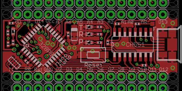
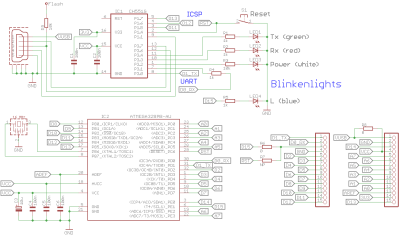
The PCB manufacturing for the Arduino Nano currently places components on both sides of the board, requiring two operations for solder paste, pick-and-place, and reflow. Naturally this increases costs, simply designing a two-layer PCB with components on top lowers the price of manufacturing.

Since the ATmega328PB was released, it has proven to be a better and cheaper MCU for manufacturing than the ATmega328P, the current MCU used by the Arduino Nano and clones. While the newer MCU is not backwards compatible like its predecessor, it has additional UART, GPIO, counters, and other features that allow users to take advantage of new libraries and peripherals.

Rather than featuring the typical voltage regulator used by Arduino boards (used to allow the board to be powered by a voltage source greater than 5V), a switching regulator allows for less energy loss but a higher component cost. A better solution than both of these would be to simply not have a voltage regulator. While this may be controversial, there are sufficient battery power sources for this design to work (4 cells of AA or AAA NiMh batteries or a mobile phone charger).

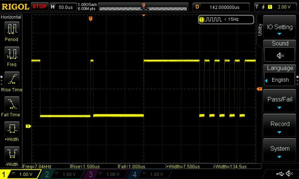
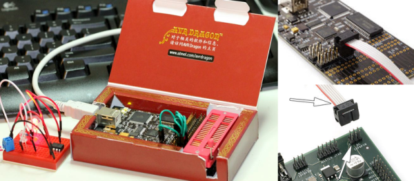
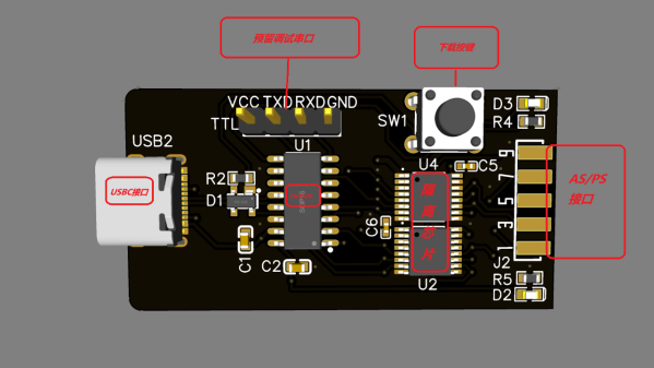
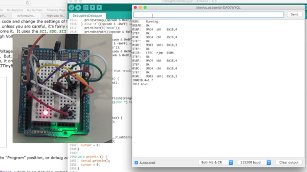
The Arduino Nano uses a bootloader for handling programming the MCU, which requires the USB to serial bridge to be disconnected from anything that could interfere with the programming. Thus, programs using the COM port on the computer must release the port, including the serial monitor. Rather than using the bootloader, ICSP (in-circuit serial programming) and DebugWire are possible alternatives that connect the ICSP pins to the CH551 development board or programming via the reset pin.

There are a number of other spec and firmware improvements suggested in the writeup, as well as comparison between the Arduino Nano, Arduino Every, and Chinese clones. It’s definitely worth a look!

Debugging Arduino Is Painful: This Can Help

If you are used to coding with almost any modern tool except the Arduino IDE, you are probably accustomed to having on-chip debugging. Sometimes having that visibility inside the code makes all the difference for squashing bugs. But for the Arduino, most of us resort to just printing print statements in our code to observe behavior. When the code works, we take the print statements out. [JoaoLopesF] wanted something better. So he created an Arduino library and a desktop application that lets you have a little better window into your program’s execution.

To be honest, it isn’t really a debugger in the way you normally think of it. But it does offer several nice features. The most rudimentary is to provide levels of messaging so you can filter out messages you don’t care about. This is sort of like a server’s log severity system. Some messages are warnings and some are informational, and some are verbose. You can select what messages to see.

In addition, the library timestamps the messages so you can tell how much time elapsed between messages and what function you were in during the message. It can also examine and set global variables that you preconfigure and set watches on variables. It is also possible to call functions from the serial monitor.

Continue reading “Debugging Arduino Is Painful: This Can Help”

Debugging An Arduino With An Arduino

As every Hackaday reader knows, and tells us at every opportunity in the comments, adding an Arduino to your project instantly makes it twice as cool. But what if, in the course of adding an Arduino to your project, you run into a problem and need to debug the code? What if you could use a second Arduino to debug the first? That would bring your project up to two Arduinos, instantly making it four times as awesome as before you started! Who could say no to such exponential gains?

Debugging an ATTiny85

Not [Wayne Holder], that’s for sure. He writes in to let us know about a project he’s been working on for a while that allows you to debug the execution of code on an Arduino with a second Arduino. In fact, the target chip could even be another AVR series microcontroller such as a the ATTiny85. With his software you can single-step through the code, view and modify values in memory, set breakpoints, and even disassemble the code. Not everything is working fully yet, but what he has so far is very impressive.

The trick is exploiting a feature known as “debugWIRE” that’s included in many AVR microcontrollers. Unfortunately documentation on this feature is hard to come by, but with some work [Wayne] has managed to figure out how most of it works and create an Arduino Sketch that lets the user interact with the target chip using a simple menu system over the serial monitor, similar to the Bus Pirate.

[Wayne] goes into plenty of detail on his site and in the video included after the break, showing many of the functions he’s got working so far in his software against an ATTiny85. If you spend a lot of time working on AVR projects, this looks like something you might want to keep installed on an Arduino in your tool bag for the future.

Debugging microcontroller projects can be a huge time saver when your code starts running on real hardware, but often takes some hacking to get working.

Continue reading “Debugging An Arduino With An Arduino”

OBDII to Speed Pulse: Atmel ICE

Building An OBD Speed Pulse: Behold The ICE

I am a crappy software coder when it comes down to it. I didn’t pay attention when everything went object oriented and my roots were always assembly language and Real Time Operating Systems (RTOS) anyways.

So it only natural that I would reach for a true In-Circuit-Emulator (ICE) to finish of my little OBDII bus to speed pulse generator widget. ICE is a hardware device used to debug embedded systems. It communicates with the microcontroller on your board, allowing you to view what is going on by pausing execution and inspecting or changing values in the hardware registers. If you want to be great at embedded development you need to be great at using in-circuit emulation.

Not only do I get to watch my mistakes in near real time, I get to make a video about it.

Getting Data Out of a Vehicle

I’ve been working on a small board which will plug into my car and give direct access to speed reported on the Controller Area Network (CAN bus).

To back up a bit, my last video post was about my inane desire to make a small assembly that could plug into the OBDII port on my truck and create a series of pulses representing the speed of the vehicle for my GPS to function much more accurately. While there was a wire buried deep in the multiple bundles of wires connected to the vehicle’s Engine Control Module, I have decided for numerous reasons to create my own signal source.

At the heart of my project is the need to convert the OBDII port and the underlying CAN protocol to a simple variable representing the speed, and to then covert that value to a pulse stream where the frequency varied based on speed. The OBDII/CAN Protocol is handled by the STN1110 chip and converted to ASCII, and I am using an ATmega328 like found on a multitude of Arduino’ish boards for the ASCII to pulse conversion. I’m using hardware interrupts to control the signal output for rock-solid, jitter-free timing.

Walk through the process of using an In-Circuit Emulator in the video below, and join me after the break for a few more details on the process.

Continue reading “Building An OBD Speed Pulse: Behold The ICE”