Supercon 2022: [Liz McFarland] Builds Golden Wings, Shows You How

Are you, by any chance, wondering about giving yourself wings? You should listen to [Liz McFarland] sharing her experience building a Wonder Woman suit, and not just any – the Golden Eagle suit from Wonder Woman 1984, adorned with a giant pair of wings. If a suit like that is in your plans, you’ll be warmly welcomed at a cosplay convention – and [Liz] had her sights on the San Diego Comic Con. With an ambitious goal of participating in the Comic Con’s cosplay contest, the suit had to be impressive – and impressive, it indeed was, not just for its looks, but for its mechanics too.

[Liz] tells us everything – from producing the wings and painting them, to keeping them attached to the body while distributing the weight, and of course, things like on-venue nuances and safety with regards to other participants. The dark side of cosplay building reality isn’t hidden either – talking, of course, about the art of staying within a reasonably tight budget. This build takes advantage of a hackerspace that [Liz] is an active member in – the [Crash Space] in LA. Everything is in – lasercutting, 3D printing, and even custom jigs for bending wing-structual PVC pipes play a role.

It would have been a travesty to not have the wings move at will, of course, and [Liz] had all the skills you could want for making the wings complete. She went for two linear actuators, walking us through the mechanical calculations and considerations required to have everything fit together. It’s not easy to build a set of wings on its own, let alone one that moves and doesn’t crumble as you use it – if you have already attempted bringing mechanical creations like this into life, you can see the value in what [Liz] shares with us, and if you haven’t yet delved into it, this video will help you avoid quite a few pitfalls while setting an example you can absolutely reach.

The suit was a resounding success at the con, and got [Liz] some well-earned awards – today, the suit’s story is here for the hackers’ world. Now, your cosplay aspirations have an inspiring real-life journey to borrow from, and we thank [Liz] for sharing it with us.

Continue reading “Supercon 2022: [Liz McFarland] Builds Golden Wings, Shows You How”

Supercon 2022: [Jorvon Moss] Gives His Robots A Soul

How do you approach your robot designs? Maybe, you do it from a ‘oh, I have these cool parts’ position, or from a ‘I want to make a platform on wheels for my experiments’ perspective. In that case, consider that there’s a different side to robot building – one where you account for your robot’s influence on what other people around feel about them, and can get your creations the attention they deserve. [Jorvon ‘Odd-Jayy’ Moss]’s robots are catchy in a way that many robot designs aren’t, and they routinely go viral online. What are his secrets to success? A combination of an art background, a Bachelor of Fine Arts in illustration, and a trove of self-taught electronics skills helped him develop a standout approach to robot building.

Now, [Jorvon] has quite a few successful robot projects under his belt, and at Supercon 2022, he talks about how our robots’ looks and behaviour shapes their perception. How do your own robots look to others, and what feelings do they evoke? With [Jorvon], you will go through fundamentals of what makes a robot look lively, remarkable, catchy or creepy, and it’s his unique backgrounds that let him give you a few guidelines on what you should and should not do when building a certain kind of robot.

You’ll do good watching this video – it’s short and sweet, and shows you a different side to building robots of your dreams; plus, the robot riding around on the stage definitely makes this presentation one of a kind. No matter your robot’s technical complexity, it’s significant that it can make people go ‘wow’ when they see it. Not all robots are there to single-mindedly perform a simple task, after all – some are meant to travel around the world.

Continue reading “Supercon 2022: [Jorvon Moss] Gives His Robots A Soul”

Share Your Projects: Making Helpful PCBs

When it comes to things that hackers build, PCBs are a sizeable portion of our creative output. It’s no wonder – PCB design is a powerful way to participate in the hardware world, making your ideas all that more tangible with help of a friendly PCB fab. It’s often even more lovely when the PCB has been designed for you, and all you have to do is press “send” – bonus points if you can make a few changes for your own liking!

A lot of the time, our projects are untrodden ground, however, and a new design needs to be born. We pick out connectors, work through mechanical dimensions, figure out a schematic and check it with others, get the layout done, and look at it a few more times before sending it out for production. For a basic PCB, that is enough – but of course, it’s no fun to stop at ‘basic’, when there’s so many things you can do at hardly any cost.

Let’s step back a bit – you’ve just designed a board, and it’s great! It has all the chips and the connectors you could need, and theoretically, it’s even supposed to work first try. Now, let’s be fair, there’s an undeniable tendency – the more PCBs you design, the better each next one turns out, and you learn to spend less time on each board too. As someone with over two hundred PCBs under her belt, I’d like to show you a bunch of shortcuts that make your PCB more helpful, to yourself and others.

There’s a few ways that you can share your PCB projects in a more powerful way – I’d like to point out a few low-hanging fruits, whether README.md files or markings on the PCB itself. I’ve been experimenting quite a bit with external and embedded documentation of PCBs, as well as PCB sharing methods, got some fun results, and I’d like to share my toolkit through a few punchy examples and simple tricks. I’d also like to hear about yours – let’s chat! Continue reading “Share Your Projects: Making Helpful PCBs”

FET: Fun Endeavors Together

Last time, we’ve looked over FET basics, details, nuances and caveats. Basics aren’t all there is to FETs, however – let’s go through real-world uses, in all their wonderful variety! I want to show you a bunch of cool circuits where a friendly FET, specifically a MOSFET, can help you – and, along the way, I’d also like to introduce you to a few FETs that I feel like you all could have a good long-term friendship with. If you don’t already know them, that is!

Driving Relays

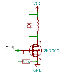
Perhaps, that’s the single most popular use for an NPN transistor – driving coils, like relays or solenoids. We are quite used to driving relays with BJTs, typically an NPN – but it doesn’t have to be a BJT, FETs often will do the job just as fine! Here’s an N-FET, used in the exact same configuration as a typical BJT is, except instead of a base current limiting resistor, we have a gate-source resistor – you can’t quite solder the BJT out and solder the FET in after you have designed the board, but it’s a pretty seamless replacement otherwise. The freewheel (back EMF protection) diode is still needed for when you switch the relay and the coil produces wacky voltages in protest, but hey, can’t have every single aspect be superior.

The reason you can drive it the same way is quite simple: in the usual NPN circuit, the relay is driven by a 3.3 V or a 5 V logic level GPIO, and for small signal FETs, that is well within Vgs. However, if your MCU has 1.8 V GPIOs and your FET’s Vgs doesn’t quite cut it, an NPN transistor is a more advantageous solution, since that one will work as long as you can source the whatever little current and the measly 0.7 V needed.

Continue reading “FET: Fun Endeavors Together”

FET: The Friendly Efficient Transistor

If you ever work with a circuit that controls a decent amount of current, you will often encounter a FET – a Field-Effect Transistor. Whether you want to control a couple of powerful LEDs, switch a USB device on and off, or drive a motor, somewhere in the picture, there’s usually a FET doing the heavy lifting. You might not be familiar with how a FET works, how to use one and what are the caveats – let’s go through the basics.

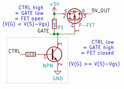
Here’s a simple FET circuit that lets you switch power to, say, a USB port, kind of like a valve that interrupts the current flow. This circuit uses a P-FET – to turn the power on, open the FET by bringing the GATE signal down to ground level, and to switch it off, close the FET by bringing the GATE back up, where the resistor holds it by default. If you want to control it from a 3.3 V MCU that can’t handle the high-side voltage on its pins, you can add a NPN transistor section as shown – this inverts the logic, making it into a more intuitive “high=on, low=off”, and, you no longer risk a GPIO!

This circuit is called a high-side switch – it enables you to toggle power to a device at will through a FET. It’s the most popular usecase for a FET, and if you’re wondering more about high-side switches, I highly recommend this brilliant article by our own [Bil Herd], where he shows you high-side switch basics in a simple and clear way. For this article, you can use this schematic as a reference of how FETs are typically used in a circuit.

Continue reading “FET: The Friendly Efficient Transistor”

Share Your Projects: Take Pictures

Information is diesel for a hacker’s engine, and it’s fascinating how much can happen when you share what you’re working on. It could be a pretty simple journey – say, you record a video showing you fixing your broken headphones, highlighting a particular trick that works well for you. Someone will see it as an entire collection of information – “if my headphones are broken, the process of fixing them looks like this, and these are the tools I might need”. For a newcomer, you might be leading them to an eye-opening discovery – “if my headphones are broken, it is possible to fix them”.

There’s a few hundred different ways that different hackers use for project information sharing – and my bet is that talking through them will help everyone involved share better and easier. Let’s start talking about pictures – perhaps, the most powerful tool in a hacker’s arsenal. I’ll tell you about all the picture-taking hacks and guidelines I’ve found, go into subjects like picture habits and simple tricks, and even tell you what makes Hackaday writers swoon!

To start with, here’s a picture of someone hotwiring a car. This one picture conveys an entire story, and a strong one.

Continue reading “Share Your Projects: Take Pictures”

One of the PCB projects involved being held in the author's hands - a large-ish green board, with two Pi Picos visible on it

RP2040 And 5V Logic – Best Friends? This FX9000P Confirms!

Over the years, we’ve seen some modern microcontrollers turn out to be 5V-tolerant – now, RP2040 joins the crowd. Half a year ago, when we covered an ISA card based on a Pi Pico, [Eben Upton] left a comment saying that RP2040 is, technically, 5V tolerant for GPIO input purposes. The datasheets don’t state this because the reality of 5V tolerance isn’t the same as for natively 5V-tolerant chips – for instance, it doesn’t extend all the way to 5.5V for it to be ‘legally’ 5V-tolerant, as in, what 5V tolerance typically means when mentioned in a datasheet.

Having read that comment, [Andrew Menadue] has set out to test-drive the RP2040 GPIO capabilities, in a perfectly suited real-world scenario. He’s working with retro tech like Z80-era computers, using RP2040 boards for substituting entire RAM and ROM chips that have died in his FX9000P. Not only do the RP2040-driven replacements work wonders, using RP2040 boards also turns out to be way cheaper than sourcing replacements for chips long out of production!

Previously, [Andrew] used level shifter chips for interfacing the RP2040 with 5V systems, but he’s rebuilt a few designs of his without level shifters for the sake of this experiment. Now, he reports that, so far, those boards have been running long-term without problems. Together with [Eben]’s comment, this instills confidence in us when it comes to our RP2040 forays and 5V inputs.

There are a number of important caveats to this, that you should read up on. Some major points – certain GPIOs (like ADC ones) can’t take it, the GPIOs aren’t 5V-tolerant when set to output, and you shouldn’t feed the GPIOs 5V when the RP2040’s VDDIO is not powered up. [Andrew] points out one such case himself – one board of his has shed all level shifters except for the 8-bit address bus, which is driven by either the CPU or the RP2040 at different times, and that would result in 5V on an output-set GPIO when contention happens. All in all, if you’re working with 5V logic and your application is more hacking than business-critical stuff, you can shed the level shifters, too.

Continue reading “RP2040 And 5V Logic – Best Friends? This FX9000P Confirms!”