The cheapest PCBs – and therefore most common – are green solder mask with white silkscreen. It works, but it’s also incredibly boring. This is the way things were done up until a few years ago with the explosion of board houses trying to compete for your Yuan, and now getting a red, yellow, black, blue, green, and even OSH purple is possible. This doesn’t mean multiple solder masks aren’t possible, as [Saar] demonstrates with his demonstration of multicolor solder masks and circuit love.
Althought Eurocircuits has PCB PIXture, a tool for putting graphics on PCBs, [Saar] made this with his own tool, PCBmodE. The design of both the red and yellow variants are abstract, and only meant to be a demonstration of what can be done with multicolor solder mask. It looks great with five backlit LEDs, and with an acrylic top and bottom, makes a great coaster or art piece.
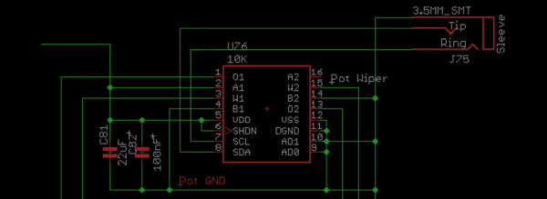
Those twisty knobs connected to potentiometers aren’t necessarily a strict linear progression from one resistance to another. Potentiometers have a taper. Yes, sometimes it’s a linear taper that’s a straight line from one resistance to another, but you can find log (audio) taper pots, and anti-log taper pots. It’s been this way for a hundred years, and now we have a pot with a digitally controllable taper thanks to a guitar pedal that fits in your shoe.
For the last few years, [John] has been hard at work creating the SoulPedal, a shoe insert that’s the wireless, wearable alternative to expression pedals, wah pedals, and every other guitar effects pedal that uses an ankle. [John] got the idea by replacing the light-sensitive resistor in a wah pedal with a force sensitive resistor in his shoe. It worked, but there were wires. Now the SoulPedal is based on a TI SoC +Radio with all the niceties you would expect.
When designing the ‘base station pedal’, [John] realized he had a digital pot with two channels, and the entire device only uses one of these channels. Instead of letting that little bit of silicon go to waste, [John] wired these two digital pots in parallel, allowing the user to customize the taper of a digital pot. If you’re asking yourself, ‘why’, the answer is, ‘because he could.’
It’s an interesting application for sure, and while this digitally controllable pot can replicate the linear, log, and anti-log tapers, the really interesting thing will be to see what non-standard tapers sound and feel like.
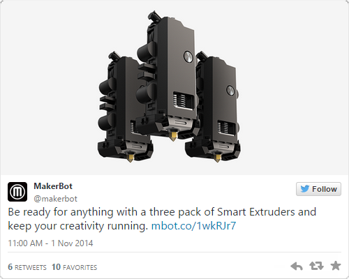
A direct link to Makerbot’s 3-pack of Smart Extruders is very hard to find
It’s been a little over a year since Makerbot introduced their new line of printers, and since then there have been grumblings about the quality of the Smart Extruder that each one of these printers comes with. While there is no 3D printer extruder that will not eventually clog, wear down, or otherwise break, there are reports of the Makerbot Smart Extruder failing in only hundreds or even tens of hours of use. Considering that a single large print can take a dozen or so hours to complete, you can easily see the why the Smart Extruder is so despised and why even the availability of a three-pack of Smart Extruders is a joke in the 3D printing community.
Of course a cheap shot at Makerbot that plays right into your preconceived ideas and prejudices is far too easy. We’re here to solve problems, not just state them, so here’s what we’re working with: to quantify the long-term reliability of 3D printers we need a way to measure the mean time before failure of extruders. This is already a solved problem; it’s just not implemented.
On aircraft and some very expensive engines that power things like buildings and ships, there’s one gauge, tucked away in the control panel, that keeps track of how long the engine has been running. It’s called a hobbs meter, and the idea behind it is extremely simple – when there is power going to the Hobbs meter, it counts out hours on a small clockwork display. The resolution of the display is only tenths of an hour, usually, but that’s good enough for scheduling maintenance and to be mentioned in NTSB accident reports.
Spend enough time with a 3D printer, and you’ll quickly realize the ‘estimated print time’ is merely a ballpark, and with failed prints the ‘total print time for this object’ isn’t exactly a perfect measure of how many hours you’ve been using your extruder. Only by directly measuring how many hours are logged on a hot end or how many kilometers of filament have been sent through an extruder will you ever get an accurate idea of how long an extruder has been running, and how reliable a printer is.
Hobbs meters are available from Mouser, but you’ll be overpaying there. The better option is from a vendor in a different niche; $30 for a meter that can connect directly to the extruder heater. If enough people add this and keep proper logs, there’s a slight chance of improving the state of 3D printers with real data and not the prejudices of people trying to justify their own designs and purchases.
But perhaps that’s too hard; adding a $30 item to a printer’s BOM just for the sake of data is a bit much. Luckily, there’s an even simpler solution that won’t cost a dime. Just measure the time a heater has been on in the firmware, or save the total length of extruded filament in a microcontroller’s EEPROM. Every printer firmware out there, from Marlin to Repetier to Sprinter has in it a way to calculate both the length of time a heater has been on or how much filament has been pushed through a nozzle.
However, this is 3D printing we’re dealing with. An organized community is not a luxury we currently enjoy, and for this to work several things are needed. The first is somewhere to upload failure statistics. This would be a web site, naturally, with the ability to input the printer make, extruder and hot end model, and the time since last clogged nozzle. The website itself is just a database, some JavaScript, a bit of CSS, and some hosting costs; not hard until you consider tens of thousands of operators would have to know about this website and contribute.
Secondly, if we’re not going with mechanical Hobbs meters there would need to be a ‘total time heater on’ or ‘total length of extruded filament’ variable in the various firmwares. There would hopefully be standardized Gcodes or Mcodes to read and reset this variable.
Will this happen? Of course not. Organization isn’t a strong suit of the RepRap project, and any company that implements Hobbs meter functionality will probably lock that up in proprietary obfuscation. However, Makerbot isn’t dumb, and given they’re selling three-packs of extruders, I would bet they have some data on the MTBF of their extruders. A community-based measurement of the most common cause of broken printers is certainly possible, but like all problems it’s one of organization, not technology.
3D Printering is a semi-weekly column that digs deep into all things related to 3D Printing. If you have questions or ideas for future installments please sending us your thoughts.
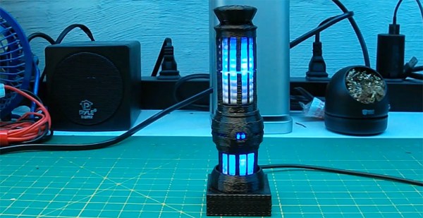
Designed in the 2350s at the Utopia Planita shipyards, the warp core found in Galaxy class starships Yamoto, Odyssey, Challenger, and yes, Enterprise was a incomparable work of engineering, leading to more than one Daystrom Prize for its development. We’re still at least fifteen years away from the great [Zefram Cochrane]’s birth – and another 200 years until [Richard Daystrom] is born – but now, thanks to our advanced technology, a miniature warp core is within reach.
About a year ago, [Alex] found a warp core table lamp based on the one found on the Enterprise. it called out to him, but it’s a an extremely large build and only having a Solidoodle 2 as a 3D printer, [Alex] decided to scale it down to 25%.
Inside the warp core are a few Neopixel strips driven by a 5V Trinket. It’s not the ideal solution – if all the LEDs are turned on at the same time, the Trinket will brown out. It’s enough for an accurate pulsating effect, though, and was a nice enough gift to appease even the most discerning Trek fans he gave these mini models to.
Hackaday.io, our neat project hosting site, has been around for a little more than a year. It’s been public for juuussst over 11 months, and today we’ve hit a milestone: we have over 50,000 hackers on board, documenting their builds and giving skulls for the cool projects they find. The lucky 50,000th hacker? This guy.
All of this wouldn’t be possible without those 50,000 people on Hackaday.io. This one is for everybody out there who’s already registered. We have to give a shoutout to [Dave Darko], by far the most helpful guy on the entire site. He has been a thorn in the side of the devs, giving us an amazing amount of feedback.
Speaking of devs, we’re going to be giving out a t-shirt and a few goodies for the 65,536th hacker to sign on (yes, an off-by-one error), for being the person who forced us to refactor everything. Considering the backroom planning, that shouldn’t be long. If you’re one of the nearly 200,000 unregistered users who visited over the last 30 days, there’s a tiny incentive to sign up.
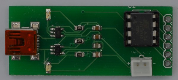
Since just about everyone who would be interested in electronics has a decent cellphone now, there’s an idea that we don’t need USB or weird serial adapters anymore. Bluetooth LE is good enough for short-range communication, and there are a ton of boards and Kickstarter projects out there that are ready to fill the need.
This board was developed as a means to connect sensors for a vintage motorcycle to an iOS device for display and data logging. A small, cheap board was needed that could be powered by a LiPo battery, and [Micah] created a board that fit his needs perfectly.
Four of the six IO pins on the ‘Tiny85 are broken out on a pin header; two are used to communicate with the BTLE module. It’s simple, fairly cheap, and can be powered by a battery. Exactly what you need if you want a wireless sensor board. All the files can be found in the Git repo and everything is open source. Not bad.
Network Analyzers are frequently used for measuring filters, making them extremely valuable for building radios and general mucking about with RF. They are, however, extremely expensive. You can, however, build one in an Altoids tin with an Arduino Nano, a small screen, and an AD9850 frequency synthesis module picked up on eBay.
The basic idea behind a network analyzer is to feed a frequency into a device, and measure the amplitude coming out of the device, and plot this relationship over a frequency. [Bill Meara] has been a human network analyzer before, changing frequencies and plotting the output of devices under test by hand. [DuWayne] (KV4QB) build a device to automate the entire process.
The block diagram is easy enough – an AD9850 sends a signal to the device, and this is measured by the Arduino with a small amplifier. The signal is measured again when it comes back from the device under test, and all this is plotted on a small display. Simple, and [DuWayne] is getting some very good readings with a lowpass filter and crystal filter made on a small solderless breadboard.