Disguising The PS5 With A Custom Wood And Carbon Fiber Enclosure

The PlayStation 5 has a very distinctive enclosure that some love and others hate. Its design certainly does not lend itself to lying on its side, even though this is a more practical orientation for putting on a shelf in a TV console. [Matt] from [DIY Perks] decided to address this and built a custom wood and carbon fiber PS5 enclosure that looks good in any orientation.

He started by disassembling his PS5 and taking out only the main electronics unit, fan, and power supply. These were mounted on a carbon fiber baseplate using hexagonal threaded standoffs. The sides of the enclosure were constructed from dark walnut, with holes cut in the front and back for connectors and airflow. A long recess was cut in the front hole and covered with an ingenious carbon fiber cover which opens if you press it at one end and acts as the power button if you press it at the other end.

Matt paid close attention to the airflow routing of the original enclosure and copied it to the new one. Like the original, he used adhesive foam strips to direct the air through the heat sinks. The top cover is also carbon fiber, with an elegant honeycomb hole pattern with wood inserts for the air intake.

This is not [Matt]’s first custom PS5 enclosure. The other was a significantly more flashy brass incarnation of the original. Other custom enclosure he’s made include a wood PC case and a brass encased USB-C monitor. Continue reading “Disguising The PS5 With A Custom Wood And Carbon Fiber Enclosure”

3D Printed Joystick Using Spherical Flexure Joint

One of the many advancements brought about by 3D printing is the rapid development of compliant mechanisms and flexure joints. One such example is [jicerr]’s joystick, which uses a pair of spherical flexure joints recently developed by researchers from Delft University of Technology in the Netherlands, See the videos after the break.

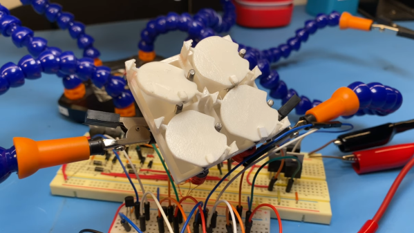
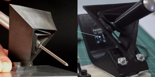
Both flexure joint designs make use of tetrahedron-shaped elements, allowing an object to pivot around a fixed point in space like a ball-and-socket joint. One of the joints, named Tetra 2, is perfect for printing on a standard FDM printer, and the 3D files were uploaded to Thingiverse by [Jelle_Rommers], one of the researchers. [jicerr] took the design and created a base to mount an HMC5883 3-axis magnetometer a short distance from the focal point, which senses the rotation of a small magnet at the focal point. An Arduino takes the output from the magnetometer, does the necessary calculation, and interfaces to a PC as a joystick. Demonstrates this by using it to rotate and pan the design in Solidworks. One thing to keep in mind with this design is that it needs a fixed base to prevent it from moving around. It should also be possible to integrate the design directly into the housing of a controller.

Another amusing application is to turn it into a pen holder with a chicken head on the front, as demonstrated by [50Pro]. If you have any ideas for other applications, drop them in the comments.

Compliant mechanisms have a number of interesting applications, including harmonic drives, dial indicators and thrust vectoring mounts.

Continue reading “3D Printed Joystick Using Spherical Flexure Joint”

A High Torque 3D Printed Harmonic Drive

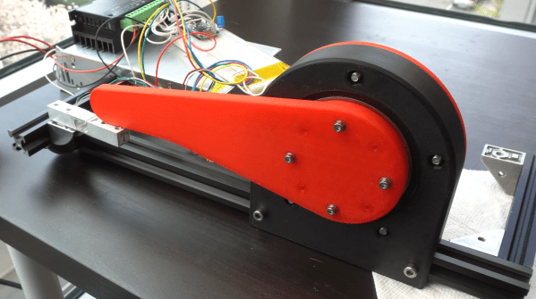
Actuators that are powerful, accurate, compact, and cheap are like unicorns. They don’t exist. Yet this is what [3DprintedLife] needed for a robotic camera arm, so he developed a custom 3D printed high torque strain wave gearbox to be powered by a cheap NEMA23 stepper motor.

Strain wave gears, otherwise known as harmonic drives, are not an uncommon topic here on Hackaday. The work by deforming a flexible toothed spline with a rotating elliptical part, which engages with the internal teeth of an outer spline. The outer spline has a few more teeth, causing the inner spline to rotate slowly compared to the input, achieving very high gear ratios. Usually, the flexible spline is quite long to allow it to flex at one end while still having a rigid mounting surface at the other end. [3DprintedLife] got around this by creating a separate rigid output spline, which also meshes with the flexible spline. Continue reading “A High Torque 3D Printed Harmonic Drive”

A High Power Wood Rocket In 5 Days

Getting started with model rocketry is relatively cheap and easy, but as you move up in high power rocketry, there are a few hoops to jump through. To be able to buy rocket motors larger than H (160 N·s / 36 lbf·s impulse) in the US, you need to get certified by the National Association of Rocketry. The main requirement of this certification involves building, flying, and recovering a rocket with the specific motor class required for the certification level. [Xyla Foxlin] had committed to doing her Level 2 certification with a couple of friends, thanks to the old procrastination monster, was forced to build a rocket with only 5 days remaining to launch data.

For Level 2 certification, the rocket needs to fly with a J motor, which is capable of producing more than 640 N·s of impulse. Fortunately [Xyla] had already designed the rocket in OpenRocket, and ordered the motor and major body, nosecone, and parachute components. The body was built around 2 sections of 3″ cardboard tubes, which are covered in a few layers of fiberglass. The stabilizing fins were laser cut from cheap plywood and were epoxied to the inner tube which holds the motor and passes through the sides of the outer tube. The fins are also fibreglassed to increased strength. For a unique touch, she covered the rocket with a real wood veneer, with the rocket’s name, [Fifi], inlaid with darker wood. The recovery system is a basic parachute, connected to the rocket body with Kevlar rope.

[Xyla] finished her rocket just in time for the trek out to the rocket range. She successfully did the certification flight and recovered [Fifi] in reusable condition, which is a requirement. There was nothing groundbreaking about [Fifi], but then again, reliability the main requirement. You don’t want to do a certification with a fancy experimental rocket that could easily fail. Continue reading “A High Power Wood Rocket In 5 Days”

Actively Balancing A Robot With A Gyroscope

Self-balancing robots are a common hacker project, but we don’t often see them using spinning gyroscopes to achieve that balance. Robot master [James Bruton] decided to build a robotic platform with active gyroscopic stabilization, starting from a simple proof of concept.

A gyroscope can balance, but cannot actively counteract external forces directly. However, if the gyroscope is tilted around an axis it will exert a force perpendicular to that axis of tilt, known as gyroscopic precession. By tilting the gyroscope with an actuator, and orienting the gyroscope correctly, gyroscopic precession can be used for stabilization. This is known as a control moment gyroscope. [James] demonstrated this with a 3D printed proof of concept, which is used as an IMU to measure the angle of tilt, and use a PID loop to correct the imbalance with a servo actuating the gyroscope.

His second platform used a pair of gyroscopes spinning in opposite directions to compensate for any unintended gyroscopic precession along another axis. A pair of roller skate wheels allow the entire platform to roll along. Due to a slight imbalance in the platform, [James] noticed that the gyroscopes will continue to creep in one direction, until reaching the end-stops and falling over. By adding a second software controller to keep track of how much the gyroscopes have to move to maintain balance, it can continuously calculate and update the balancing point. This prevents the gyroscopes from hitting the end stops.

Control moment gyroscopes are commonly used for attitude control on spacecraft, and to reduce the rolling motion of boats in waves. [James] has plans to combine a control moment gyroscope with the more conventional balancing method, to balance a robot on a single wheel.

We’ve seen a two wheeled RC cars use gyroscopes before, but without the active control part.
Continue reading “Actively Balancing A Robot With A Gyroscope”

Homemade Metal Band Saw

As the channel name implies, [Workshop From Scratch] is building a growing list of tools and machines from scratch. His latest edition is a heavy-duty metal band saw.

As with all his tools, the frame consists of thick welded steel components. The blade runs on a pair of modified belt pulleys and is driven by a motor with a worm gearbox. The blade tension is adjustable, and so are the pair of blade guides. To slowly lower the blade while cutting, [Workshop From Scratch] added a hydraulic piston with an adjustable valve to limit the lowering speed. When it reaches the bottom, a limit switch turns off the motor. The saw is mounted on a heavy steel table and can rotate at the base to cut at different angles. A heavy-duty vise, also built from scratch holds the workpieces securely in place.

Judging by the amount of steel he cuts for his projects, we imagine this saw will be a welcome addition to the shop. It’s impressive what he is able to build with just a drill, angle grinder, and welder. Many of the other tools used in the video, like the magnetic drill press and hydraulic vise are also his handiwork. Continue reading “Homemade Metal Band Saw”

Adding MQTT To A Solar Powered PIR Light

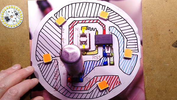
The size and price of the ESP wifi modules have quickly made them into one of the preferred building blocks for IoT devices. Unfortunately they are not particularly well suited for very low power applications.  [LittlePetieWheat] wanted to add MQTT to a cheap PIR solar light, so he paired an ESP with an Attiny85 to hold it to a strict power budget.

Most of these lights contain some sort of no-name microcontroller that monitors the analog PIR sensor, and turns on the LEDs as required. [LittlePetieWheat] replaced the PIR sensor with one that gives a digital output for simpler interfacing. The Attiny serves as the low power brains of the project. Its tasks include reading the solar panel and battery voltages, and PIR output. When movement is detected by the sensor, it activates a clever little latching power circuit to power on the ESP01 just long enough to send a MQTT message. The LEDs are only turned on if there is no power coming from the solar panel. The solar power is stored in a 18650 battery.

The Attiny85 might not be a powerhouse, but it is perfect for simple, low power applications like this. We’ve also seen it pushed to its limits by running tiny machine learning models, or receiving software updates over I2C. Continue reading “Adding MQTT To A Solar Powered PIR Light”