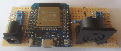
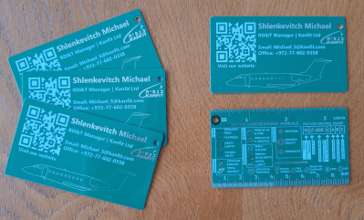
A Simple Laser Harp MIDI Instrument

Craig Lindley is a technical author and a prolific maker of things. This simple project was his first attempt to create a laser harp MIDI device. While on vacation, Craig saw a laser harp with only three strings and decided to improve upon it by expanding it to twelve strings. The principle of operation is straightforward: twelve cheap diode laser modules aim a beam towards an LDR, which changes resistance if the light level changes when the beam is interrupted.

The controller is a simple piece of perf board, with a Wemos D1 mini ESP32 module flanked by some passives, a barrel socket for power, and the usual DIN connector for connecting the MIDI instrument. Using the ESP32 is a smart choice, removing all the need for configuration and user indication from the physical domain and pushing it onto a rarely-needed webpage. After a false start, attempting to use a triangular frame arrangement, [Craig] settled upon a simple linear arrangement of beams held within a laser-cut wooden box frame. Since these laser modules are quite small, some aluminium rod was machined to make some simple housings to push them into, making them easier to mount in the frame and keeping them nicely aligned with their corresponding LDR.

Sadly, the magnetic attachment method [Craig] used to keep the LDRs in place and aligned with the laser didn’t work as expected, so it was necessary to reach for the hot glue. We’ve all done that!

An interesting addition was using an M5 stack Unit-Synth module for those times when a proper MIDI synthesiser was unavailable. Making this luggable was smart, as people are always fascinated with laser harps. That simple internal synth makes travelling to shows and events a little easier.

Laser harps are nothing new here; we have covered plenty over the years. Like this nice build, which is more a piece of art than an instrument, one which looks just like a real harp and sounds like one, too, due to the use of the Karplus-Strong algorithm to mimic string vibrations.

2024 Business Card Challenge: PCB Business Cards For Everybody

PCB business cards for electronics engineers might be very much old news in our circles, but they are still cool, not seen too much in the wild, and frankly inaccessible to those in other industries. For their entry into the 2024 Business Card Challenge, [Dima Shlenkevitch] is helping a little to alleviate this by providing a set of design examples and worked costs with suppliers.

Original green is still the cheapest option.

[Dima] lists key features every PCB business card should include, such as the expected thickness, restrictions for placing NFC components, and some aesthetics tips. Make sure to choose a supplier that allows you to remove their order number from the manufactured PCB, or it will look out of place.

Ordering PCBs with these specifications to keep costs reasonable requires effort, so [Dima] offers some example designs along with the results. If you want to have pretty gold lettering and graphics, you will need ENiG plating, increasing the price. Non-standard solder mask colors can also raise the price.

Will this help with the practical aspects of driving the PCB design software and actually placing the order? Obviously not, but the information provided gives you a leg up on some of the decisions so you don’t go down an expensive rabbit hole.

2024 Business Card Challenge: BAUDI/O For The Audio Hacker

[Simon B] enters our 2024 Business Card Challenge with BAUDI/O, a genuinely useful audio output device. The device is based around the PCM2706 DAC, which handles all the USB interfacing and audio stack for you, needing only a reference crystal and the usual sprinkling of passives. This isn’t just a DAC board, though; it’s more of an audio experimentation tool with two microcontrollers to play with.

The first ATTiny AT1614 is hooked up to a simple LED vu-meter, and the second is connected to the onboard AD5252 digipot, which together allows one to custom program the response to the digital inputs to suit the user. The power supply is taken from the USB connection. A pair of ganged LM2663 charge-pump inverters allow inversion of the 5V rail to provide the necessary -5 V for the output amplifiers.  This is then fed to the LM4562-based CMoy-type headphone amplifier.  This design has a few extra stages, so with a bit of soldering, you can adjust the output filtering to suit. An LM1117 derives 3.3 V from the USB input to provide another power rail,  mostly for the DAC.

There’s not much more to say other than this is a nice, clean audio design, with everything broken out so you can tinker with it and get exactly the audio experience you want.

Marimbatron: A Digital Marimba Prototyping Project

The Marimbatron is [Leo Kuipers] ‘s final project as part of the Fab Academy program supervised by [Prof. Neil Gershenfeld] of MIT’s Center for Bits and Atoms. The course aims to teach students how to leverage all the fab lab skills to create unique prototypes using the materials at hand.

The final polyurethane/PET/Flex PCB stack-up for the sensor pad

Fortunately, one of the main topics covered in the course is documentation, and [Leo] has provided ample material for review. The marimba consists of a horizontal series of wooden bars, each mounted over a metal resonator tube. It is played similarly to the xylophone, with a piano-type note arrangement, covering about five octaves but with a lower range than the xylophone. [Leo] converted this piano-type layout into a more logical grid arrangement. The individual pads are 3D printed in PETG and attached to a DIY piezoresistive pressure sensor made from a graphite-sprayed PET sheet laid upon a DIY flexible PCB. A central addressable LED was also included for indication purposes. The base layer is made of cast polyurethane, formed inside a 3D-printed rigid mould. This absorbs impact and prevents crosstalk to nearby sensors. The sensor PCB was initially prototyped by adhering a layer of copper tape to a layer of Kapton tape and cutting it out using a desktop vinyl cutter. While this method worked for the proof of concept, [Leo] ultimately outsourced the final version to a PCB manufacturer. The description of prototyping the sensor and dealing with over-moulding was particularly fascinating.

Continue reading “Marimbatron: A Digital Marimba Prototyping Project”

Long-Awaited SLS4All 3D Printer Now Shipping

We touched on the open source SLS4All DIY SLS 3D printer a year or two ago when the project was in the early stages. Finally, version one is complete, with a parts kit ready to ship and all design data ready for download if a DIY build or derivative is your style. As some already mentioned, this is not going to be cheap: with the full parts kit running at an eye-watering $7K before tax. But it’s possible to build or source almost all of it a bit at a time for those on a budget.

Try printing THIS benchy on an FDM machine!

It’s important to note that to access the detailed information, you’ll need to create an account, which is a bit inconvenient for an open source design. However, all the essential components seem to be available, so it’s forgivable. In terms of electronics, there are two custom PCBs: the GATE1 (GAlvo and Temperature Control) and the ZERO1 (Zero-crossing dimming) controller. Other than that, all the electronics seem to be standard off-the-shelf components. Both of these PCBs are designed using EasyEDA.

Unfortunately we couldn’t find access to the PCB Gerbers, nor does there appear to be a link to their respective EasyEDA projects, just the reference schematics. This is a bit of a drawback, but it’s something that could easily be reproduced with enough motivation. Control is courtesy of a Radxa Rock Pi, as there were ‘problems’ with a Raspberry Pi. This is paired with a 7-inch touchscreen to complete the UI. This is running a highly modified version of the Klipper together with their own control software, which is still undergoing testing before release.

The laser head is built around a 10 W 450 nm laser module from China and a high-end galvanometer set. Two 200 W halogen tube heaters heat the print bed, and 200 W silicone heating pads heat both the powder bed and the print bed.

Continue reading “Long-Awaited SLS4All 3D Printer Now Shipping”

Studying The Finer Points Of 3D Printed Gears

[How to Mechatronics] on YouTube endeavored to create a comprehensive guide comparing the various factors that affect the performance of 3D printed gears. Given the numerous variables involved, this is a challenging task, but it aims to shed light on the differences. The guide focuses on three types of gears: the spur gear with straight teeth parallel to the gear axis, the helical gear with teeth at an angle, and the herringbone gear, which combines two helical gear designs. Furthermore, the guide delves into how printing factors such as infill density impact strength, and it tests various materials, including PLA, carbon fiber PLA, ABS, PETG, ASA, and nylon, to determine the best options.

The spur gear is highly efficient due to the minimal contact path when the gears are engaged. However, the sudden contact mechanism, as the teeth engage, creates a high impulse load, which can negatively affect 
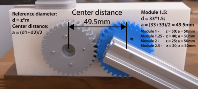
durability and increase noise. On the other hand, helical gears have a more gradual engagement, resulting in reduced noise and smoother operation. This leads to an increased load-carrying capacity, thus improving durability and lifespan.

It’s worth noting that multiple teeth are involved in power transmission, with the gradual engagement and disengagement of the tooth being spread out over more teeth than the spur design. The downside is that there is a significant sideways force due to the inclined angle of the teeth, which must be considered in the enclosing structure and may require an additional bearing surface to handle it. Herringbone gears solve this problem by using two helical gears thrusting in opposite directions, cancelling out the force.

Continue reading “Studying The Finer Points Of 3D Printed Gears”

Bidirectional Data Transfer Through Mud?

We take easy communications for granted these days. It’s no bother to turn on a lightbulb remotely via a radio link or sense the water level in your petunias, but how does a drilling rig sense data from the drill head whilst deep underground, below the sea bed? The answer is with mud pulse telemetry, about which a group of researchers have produced a study, specifically about modelling the signal impairments and strategies for maintaining the data rate and improving the signal quality.

If you’re still confused, mud pulse telemetry (MPT) works by sending a modulated pressure wave vertically through the column of mud inside the drilling tube. It’s essential to obtain real-time data during drilling operations on the exact angle and direction the drill bit is pointing (so it can be corrected) and details of geological formations so decisions can be made promptly. The goal is to reduce drilling time and, therefore, costs and minimize environmental impact — although some would strongly argue about that last point.

Continue reading “Bidirectional Data Transfer Through Mud?”