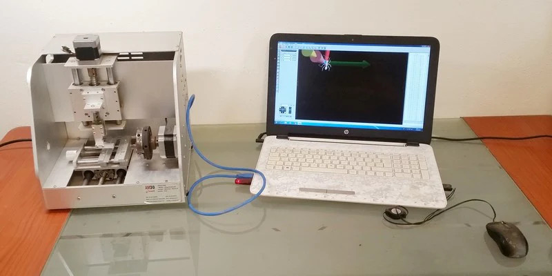
Intaglio is an ancient carving technique for adding details to a workpiece, by manually removing material from a surface with only basic hand tools. If enough material depth is removed, the resulting piece can be used as a stamp, as was the case with rings, used to stamp the wax seals of verified letters. [Nicolas Tranchant] works in the jewelry industry, and wondered if he could press a CNC engraving machine into service to engrave gemstones in a more time-efficient manner than the manual carving methods of old.
Engraving and machining generally work only if the tool you are using is mechanically harder than the material the workpiece is made from. In this case, this property is measured on the Mohs scale, which is a qualitative measurement of the ability of one (harder) material to scratch another. Diamond is the hardest known material on the Mohs scale and has a Mohs hardness of 10, so it can produce a scratch on the surface of say, Corundum — Mohs value 9 — but not the other way around.
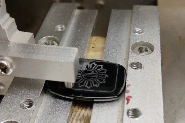
 [Nicolas] shows the results of using a diamond tip equipped CNC engraver on various gemstones typical of Intaglio work, such as Black Onyx, Malachite, and Amethyst with some details of the number of engraving passes needed and visual comparison to the same material treated to traditional carving.
Let’s be clear here, the traditional intaglio process produces deep grooves on the surface of the workpiece and the results are different from this simple multi-pass engraving method — but limiting the CNC machine to purely metal engraving duties seemed a tad wasteful. Now if they can only get a suitable machine for deeper engraving, then custom digitally engraved intaglio style seal rings could be seeing a comeback!
Intaglio isn’t just about jewelry of course, the technique has been used in the typesetting industry for centuries. But to bring this back into ours, here’s a little something about making a simple printing press.