Hackaday Prize 2023: 65uino 6502 Learning In A Familiar Package

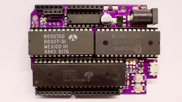
[Anders Nielsen] presents his entry for the 2023 Hackaday Prize: The 65uino. Which as you might be able to guess, is a 6502-based microcomputer wedged into an Arduino Uno form factor (well, almost wedged in, but we’ll let it slide) The premise is simple, older micros are easier to understand, the board can be build up from new-old or salvaged stock, and that’s more chips on boards and less sitting on a dusty shelf. After all, even though the 6502 in its original form is long obsolete, it’s far better to be pushing some electrons around, than sitting there decaying.

The OLED frame buffer is bigger than the host’s entire RAM. No problem!

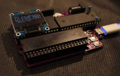
From an educational perspective, the first lesson is the hand-soldering of through-hole DIP components and a smattering of straightforward surface mount parts in their supporting roles.  Then on to setting up the cc65 toolchain. To say this is a pure 6502 system is a little misleading, it actually uses the 6507 device variant, which is a die-bond variant of the same device but with only 28 of the pins utilized.

The use of the 6532 RIOT (RAM-I/O-Timer) chip provides two 8-bit ports of GPIO as well as a timer and 128 bytes of SRAM, making the design more compact. There is a socket that will accept a 24 or 28-pin E(E)PROM device, with the extra four pins removable and the PCB snapped off if fitment into a standard ‘Uno case is desirable. Neat!

Full hardware build and PCB design (using KiCAD) are available on the 65uino GitHub page. Just remember folks, with everything minimal 6502 related — some assembly required :D

We see the 6502 a lot, let’s be fair. But why not? Here’s a slightly more practical board with a bit more resources, an absolute beast of a luggable dual-6502 machine, and yet another 6502 verilog implementation ready to be dropped into a spare corner of a FPGA project that needs a little extra.

Making Music By Probing Magnetite Crystals

Well, noises anyway. [Dmitry Morozov] and [Alexandra Gavrilova] present an interesting electronics-based art installation, which probes a large chunk of crystalline magnetite, using a pair of servo-mounted probes, ‘measuring’ the surface conductivity and generating some sound and visuals.

It appears to have only one degree of freedom per probe, so we’re not so sure all that much of the surface gets 
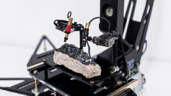
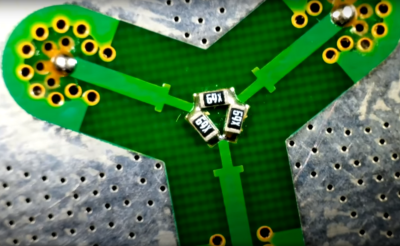
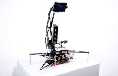
probed per run, but however it works it produces some interesting, almost random results. The premise is that the point-to-point surface resistivity is unpredictable due to the chaotically formed crystals all jumbled up, but somehow uses these measured data to generate some waveshapes vaguely reminiscent of the resistivity profile of the sample, the output of which is then fed into a sound synthesis application and pumped out of a speaker. It certainly looks fun.

From a constructional perspective, hardware is based around a LattePanda fed samples by an ADS1115 ADC, which presumably is also responsible for driving the LCD monitor and the sound system. An Arduino is also wedged in there perhaps for servo-driving duty, maybe also as part of the signal chain from the probes, but that is just a guess on our part. The software uses the VVVV (Visual Live-programming suite) and the Pure Data environment.

We haven’t seen magnetite used for this type of application before, we tend to see it as a source of Iron for DIY knifemaking, as a medium to help separate DNA or just to make nanoparticles, for erm, reasons.

Hackaday Prize 2023: Bolt Bot Micro Servo Droids

This Hackaday prize entry from [saul] is the beginning of a reconfigurable kit of 3D printed parts and servo motors for robotics learning. With just access to a printer, a few cheap-as-chips servo motors, an Arduino, and some nuts and bolts, you could be hacking together robot walkers within a few hours of starting!

Bolt Bots is very simple to understand, with all the mechanics and wiring out there in the breeze, but strictly for indoor use we reckon. If you want to add remote control to your application, then drop in one of the ubiquitous nRF24L01 boards and build yourself a copy of the remote control [saul] handily provides in this other project.

There really isn’t a great deal we can say about this, as it’s essentially a build kit with quite a few configuration options, and you just have to build with it and see what’s possible. We expect the number of parts to proliferate over time giving even more options. So far [saul] demonstrates a few flavors of ‘walkers’, a rudimentary ‘robot arm’, and even a hanging drawbot.

The bolt hardware can be found in this GitHub repo, and the remote control code in this second one.

Servo-based designs are sometimes sneered at due to their dubious accuracy and repeatability, but with a little of effort, this can be vastly improved upon. Also, multi-legged walkers need multiple servos and controllers to drive ’em. Or do they?

Continue reading “Hackaday Prize 2023: Bolt Bot Micro Servo Droids”

Arctos Robotics: Build A Robot Arm Out Of 3D Printer Spares?

ARCTOS is a 6-DOF robot arm based upon 3D printed mechanics running a modified version of GRBL firmware. Let’s get this straight now, the firmware is open source, but the hardware plans are a paid download, but for less than forty euros, we reckon the investment would be well worth it, judging from the quality of the build instructions and the software support already in place. Continue reading “Arctos Robotics: Build A Robot Arm Out Of 3D Printer Spares?”

Converting A B&W Enlarger For Colour Analog Photo Printing

[Koraks tinkers] was gifted a gargantuan photographic enlarger, a Durst Laborator 138 s, which is a unit designed specifically for black and white usage only. This was not good enough for [Koraks] so down the rabbit hole of conversion to colour we go! The moral of the story is this: if you can’t find it, build it. The hacker mentality. After wasting time and effort trying to source a period colour head for the thing, [Koraks] did the decent thing and converted what was already in front of them.

A hacked Chinese-sourced COB array. This is no use.

Now, if you’re thinking this process is simply a matter of ripping out the tungsten bulb and sticking a high-power RGB array in there, then you’re going to be disappointed! You see, colour photography of the era — specifically the RA4 process in this case — requires careful colour calibration and is heavily biased towards the red end of the visible spectrum, due to the colour curve of those tungsten bulbs we touched upon earlier.

Attempt 2: With a heavy bias towards the red end of the spectrum

The first attempt at using an off-the-shelf COB array was a bust — it simply wasn’t bright enough once the light had passed through the diffuser plate, and the light path losses were too high to expose the RA4 paper sufficiently, especially at the red end of the spectrum. Quite simply this is due to the reduced energy of red photons (compared to blue) making the desired chemical reaction rate too low. The solution is more power.

Another issue that quickly raised itself was that 8-bits of PWM control of the RGB components was inadequate since the ratio of blue to red required was so skewed, that only a few effective bits of blue channel control were usable, and that was far too granular to get the necessary accuracy.

[Koraks’] approach was to custom build an LED array with twenty red 3W LEDs and eight each of the green and blue devices. 12-bits of PWM resolution was delivered via a PCA9685 PWM controller, that also handily controlled the cooling fans. The whole thing was hooked up to an Arduino Nano, with an MCP23016 expander board performing the duty of interfacing the rotary encoders and trigger footswitch. In fact, several iterations of the LED array have been constructed and this four-part blog series (Part1, Part2, Part3, Part4) lays out the whole story in all its gory detail for your entertainment. Enjoy!

COB LED arrays are pretty nifty, checkout turning them into 7-segment displays, just because. If all you want is raw power, we reckon that 100W “should be enough for anyone…”

Thanks [macsimski] for the tip!

Update: Corrected the article header from ‘exposer head’ to ‘enlarger’ for clarity at the request of the project author.

Can You Use A POST Card With A Modern BIOS?

[Alessandro Carminati] spends the day hacking Linux kernels, and to such an end needed a decent compilation machine to chew through the builds. One day, this machine refused to boot leaving some head-scratching to do, and remembering the motherboard diagnostics procedures of old, realized that wasn’t going to work for this modern board. You see, older ISA-based systems were much simpler, with diagnostic POST codes accessible by sniffing the bus with an appropriate card inserted, but the modern motherboard doesn’t even export the same bus anymore.

See “out 0x80, al” in there? That’s a POST code being written

Do modern machines even run a POST test at all, or are there other standards? After firing up a Linux machine and dumping the first meg of memory address space, it clearly contained some of the BIOS code. [Alessandro] looked at a disassembly of the BIOS update image and saw a similar structure, with POST code data sent to port 0x80 just like machines of old.

But instead of an ISA CPU bus, we have the Low Pin Count (LPC) bus which is used to hook up the ‘super IO’ functions, controlling things such as fans, temp sensors, and other system management functions. It also serves as the connection for the TPM feature, which usually appears as one of the motherboard connectors intended to be user-accessible. It turns out that POST codes can be accessed from this point with an appropriate POST card that can talk LPC.

Continue reading “Can You Use A POST Card With A Modern BIOS?”

A 7 GHz Signal Analyser Teardown And A Trivial Repair

[Shahriar] of The Signal Path is back with another fascinating video teardown and analysis for your viewing pleasure. (Embedded below.) This time the target is an Agilent E5052A 7 GHz signal Source/Analyser which is an expensive piece of kit not many of us are fortunate enough to have on the bench. This particular unit is reported as faulty, with a signal power measurement that is completely off-the-rails wrong, which leads one to not trust anything the instrument reports.

After digging into the service manual of the related E5052B unit, [Shahriar] notes that the phase noise measurement part of the instrument is totally separate from the power measurement, only connected via some internal resistive power splitters, and this simplifies debugging a lot. But first, a short segue into that first measurement subsystem, because it’s really neat.

Cross-correlating time-gated FFT (TG-FFT) subsystem at the top, dodgy power detector at the bottom

A traditional swept-mode instrument works by mixing the input signal with a locally-sourced low-noise oscillator, which when low-pass filtered, is fed into a power meter or digitizer. This simply put, down-converts the signal to something easy to measure. It then presents power or noise as a function of the local oscillator (LO) frequency, giving us the spectral view we require. All good, but this scheme has a big flaw. The noise of the LO is essentially added to that of the signal, producing a spectral noise floor below which signals cannot be resolved.

The E5052 instrument uses a cunning cross-correlation technique enabling it to measure phase noise levels below that of its own internal signal source. The instrument houses an Oven-Compensated Crystal Oscillator (OCXO) for high stability, in fact, two from two different vendors, one for each LO, and mounted perpendicular to each other. The technique splits the input signal in half with a power splitter, then feeds both halves into identical (apart from the LOs) down-converters, the outputs of which are fed into a DSP via a pair of ADCs. Having identical input signals, but different LOs (with different phase noise spectra) turns the two signals from a correlated pair to an uncorrelated pair, with the effects of chassis vibration and gravity effects also rolled in.

The DSP subtracts the uncorrelated signal from the correlated signal, therefore removing the effect of the individual LO’s effect on the phase noise spectrum. This clever technique results in a phase noise spectrum below that of the LOs themselves, and a good representation of the input signal being measured.

This is what a DC-7GHz resistive power divider looks like. Notice the inductive matching section before each resistor branch.

Handily for [Shahriar] this complex subsystem is totally separate from the dodgy power measurement. This second system is much simpler, being fed with another copy of the input signal, via the main resistive power splitter. This second feed is then split again with a custom power divider, which upon visual inspection of the input SMA connector was clearly defective. It should not wobble. The root cause of the issue was a cold solder joint of a single SMA footprint, which worked loose over time. A little reflow and reassembly and the unit was fit for recalibration, and back into service.

We’ve seen phase noise measurements a few times on these pages, like debugging this STM32 PLL issue.

Continue reading “A 7 GHz Signal Analyser Teardown And A Trivial Repair”