NASA Hardware Techniques: Soldering Space Electronics Like It’s 1958

[PeriscopeFilms] on YouTube has many old TV adverts and US government reels archived on their channel, with some really interesting subjects to dive in to. This first one we’re highlighting here is a 1958 film about NASA Soldering Techniques (Video, embedded below), which has some fascinating details about how things were done during the Space Race, and presumably, continue to be done. The overall message about cleanliness couldn’t really be any clearer if they tried — it’s so critical it looks like those chaps in the film spend far more time brushing and cleaning than actually wielding those super clean soldering irons.

Of particular note are some of the details of wire stripping and jointing with components, such as the use of a hot-wire device to remove the insulation from wire, rather than use the kind of stripper we have lying around that cuts into the insulation and slightly distorts the wire in the process. That just won’t do. If they did have to use a cutting-type stripper, it must be precisely the right size for job, and calibrated daily.

The road to the Moon is paved with calibrated wire strippers.

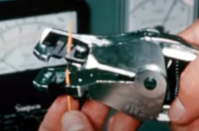
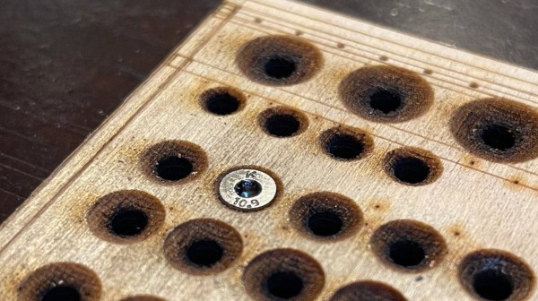
When soldering a pre-tinned wire to a leaded component, a clamp is required to prevent movement of the wire, as is a thermal shunt on the component lead to protect the delicate component from excess heat. They even specify how much to wrap a wire around a terminal to be soldered, never bending the wire more than 180 degrees.

The bottom line in all this is, is that the work must be as perfect as is possible, as there is very little chance of sending someone up to fix a dodgy soldering job, once the assembly is hurtling around the planet. They call it too much of a science to be called an art and too much art to be called a science, and we can sure appreciate that.

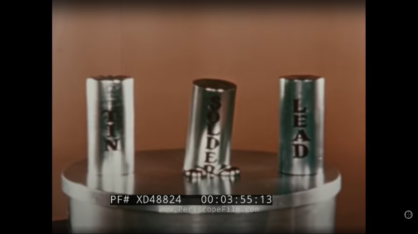
As you would expect (and it’s not exactly a big secret) NASA has some very exacting standards for assembly of all hardware, like this great workmanship standard, which is well worth studying. Soldering is an important subject for many of us, we’ve covered the subject of solder metallurgy, as well as looking at how ancient hardware hackers soldered without the benefit of much modern knowledge.

Continue reading “NASA Hardware Techniques: Soldering Space Electronics Like It’s 1958”

A V2 Rocket Inspired Steam Turbine Skateboard Is Just Around The Corner

[Integza] never fails to amuse with his numerous (and sometimes really sketchy) attempts to create usable thrust, by pretty much all means possible and the latest video (embedded below) attempting to run a reaction turbine from decomposing hydrogen peroxide, doesn’t fail to disappoint. The inspiration came from the WWII V2 rocket, which used Sodium Permanganate to breakdown Hydrogen Peroxide. This produced high pressure steam, which spun a turbine, which in turn drove the turbopumps that delivered the needed huge quantity of alcohol and liquid oxygen into the combustion chamber.

After an initial test of this permanganate-peroxide reaction proved somewhat disappointing (and messy) he moved on to a more controllable approach — using a catalytic converter from a petrol scooter in place of the messy permanganate. This worked, so the next task was to build the turbine. Naturally, this was 3D printed, and the resulting design appeared to work pretty well with compressed air as the power source. After scaling up the design, and shifting to CNC-machined aluminium, it was starting to look a bit more serious. The final test shows the turbine being put through its paces, running from the new precious metal catalyst setup, but as can be seen from the video, there is work to be done.

There appears to be a fair amount of liquid peroxide passing through into the turbine, which is obviously not desirable. Perhaps the next changes should be the mount the catalyser vertically, to prevent the liquid from leaving so easily, as well as adding some baffling to control the flow of the liquid, in order to force it to recycle inside the reaction vessel? We can’t wait to see where this goes, hopefully the steam-turbine powered skateboard idea could actually be doable? Who knows? But we’re sure [Integza] will find a way!

With steam power, there’s more than one way to get usable rotational work, like using a reciprocating engine, which can be expanded to a whole machine shop, and whilst boiling water (or catalytically decomposing Hydrogen Peroxide)  provides high pressure gas, how about just using boiling liquid nitrogen? Possibly not.

Continue reading “A V2 Rocket Inspired Steam Turbine Skateboard Is Just Around The Corner”

Quick Hacks: Countersinking Screw Heads With 3D Laser Engraving

Here’s a fun quick hack from [Timo Birnschein] about using the 3D laser engraving (or ‘stamp’ engraving) mode of certain laser cutter toolchains to create a handy countersink shape in a laser-cut and engraved workpiece. Since [Timo] uses a small laser cutter to cut out and mark project boards for their electronics builds, having an extra messy, manual countersinking operation with subsequent clean-up seemed like a waste of time and effort, if the cutter could be persuaded to do it for them.

Designs are prepared in Inkscape, with an additional ‘3D engraving’ layer holding the extra processing step. [Timo] used the Inkscape feathering tools to create a circular grayscale gradient, leading up to the central cut hole (cuts are in a separate layer) which was then fed into Visicut in order to drive the GRBL-based machine, However, you could do it with practically any toolchain that supports laser power control during a rastering operation. The results look perfectly fine for regions of the workpiece not on show, at least, but if you’re only interested in the idea from a functional point of view, then we reckon this is another great trick for the big bag of laser hacks.

There have been a great number of laser cutting hacks here over the years, since these tools are so darn useful. The snapmaker machine can be a 3D printer, a CNC cutter and a laser cutter all in one, albeit not too perfect at any of those tasks, but the idea is nice. If you own a perfectly fine 3D printer, but fancy a spot of laser engraving (and you have good eye protection!), then you could just strap a 5W blue diode laser to it and get your fix.

A Super Simple DIY Ozone Generator

[Advanced Tinkering] needed a source of fresh ozone for some future chemistry related projects, and since buying an off-the-shelf unit would be, well, just plain boring, it was obvious what to do (Video, embedded below).

Wire mesh discharge surfaces separated with a glass tube

The concept of the corona-discharge ozone generator is pretty straightforward — a high-voltage AC potential is presented over a large surface area, such that any O2 in the vicinity has the chance to get a decent dose of electrons ripping it apart and enabling the formation of the desired O3.

The construction is quite simple, just a pair of cylindrical metal wire mesh electrodes, separated by a glass tube, with a second glass tube surrounding the whole assembly. The use of high voltage AC allows the discharge to form by capacitive coupling across the central tube, giving a very simple construction. A pair of 3D-printed PLA end caps complete the reaction vessel, although it is noted in the video that the PLA is not terribly resistant to the corrosive effects of ozone, and time will tell whether these go the whole mileage.

Feed oxygen from an external generator is pumped into one end cap, at the bottom, with ozone-enriched gas passing out the other end, at the top, giving the gas a more complex path through the assembly and maximizing the contact with discharge. It will be interesting to see what the produced ozone will be used for in these future projects.

We’ve not seen a vast number of ozone hacks, but we’re no strangers to high voltage applications, like this interesting hand disinfection device, and this simple hack that generates a six-figure voltage with little more than some glasses of water, well not much more anyway.

Continue reading “A Super Simple DIY Ozone Generator”

OpenMower: Open Source Robotic Lawn Mower With RTK GPS

Robotic mowers are becoming a common sight in some places, enabled by the cost of motors and the needed control electronics being much lower, thanks to the pace of modern engineering. But, in many cases, they still appear to be really rather dumb, little more than a jacked up bump-and-go with a spinning blade. [Clemens Elflein] has taken a cheap, dumb mower and given it a brain transplant based around a Raspberry Pi 4 paired up with a Raspberry Pi Pico for the real time control side of things. [Clemens] is calling this OpenMower, with the motivation to create an open source robot mower controller with support for GPS navigation, using RTK for extra precision.

The donor robot was a YardForce Classic 500, and after inspection of the control PCB, it looks like many other robot mower models are likely to use the same controller and thus be compatible with the openmower platform. A custom mainboard houses the Pi 4 and Pico, an ArduSimple RTK GPS module (giving a reported navigational accuracy of 1 cm,) as well as three BLDC motor drivers for the wheels and rotor. Everything is based on modules, plugging into the mainboard, reducing the complexity of the project significantly. For a cheap mower platform, the Yardforce unit has a good build quality, with connectors everywhere, making OpenMower a plug and play solution. Even the user interface on top of the mower was usable, with a custom PCB below presenting some push buttons at the appropriate positions.

OpenMower mainboard

Motor control is courtesy of the xESC project, which provides FOC motor control for low cost, interfacing with the host controller via a serial link. This is worth looking into in its own right! On the software side of things, [Clemens] is using ROS, which implements the low level robot control, path planning (using code taken from Slic3r) as well a kinematics constraints for object avoidance. The video below, shows how simple the machine is to operate — just drive it around the perimeter of lawn with a handheld controller, and show it where obstacles such as trees are, and then set it going. The mower is even capable of mowing multiple lawns, making the journey between them automatically!

Robotic mower projects are not new around here, here’s the mysterious TK with an interesting take, another using RTK GPS for good (or possibly bad) and quite probably the jankiest one we’ve seen in a while, which uses a LoRa base-station to transmit RTK corrections. We’d recommend keeping well away from that last one.

Continue reading “OpenMower: Open Source Robotic Lawn Mower With RTK GPS”

Don’t Tune Your 3D Printer To Middle ‘C’ After All

Layer shift caused by the belt being way too loose.

3D printer belt tension seems like a simple thing to deal with — you set the tension and then check it’s good now and then. If it gets really loose, then the teeth can slip and you’ll get some shifts in the print, ruining it, but its an easy fix. But, we hear you ask, how do you determine what the correct tension is? Well, here’s [Lost in Tech] with a video showing some measurement techniques and analysis of a typical 3D printer, (video, embedded below) using nothing more special than a set of luggage scales. A simple theory suggested was that a tighter belt tension would result in increased radial load on the stepper motor bearings, which in turn, due to friction, would result in an increase in temperature of the motor.  After setting a few tension values on one of the belts, it was noted that tension values at the upper end of the range, resulted in a measured increased in temperature of two degrees celcius, and a large increase in noise. This can’t be good for the motor.

Continue reading “Don’t Tune Your 3D Printer To Middle ‘C’ After All”

Texture Map GCode Directly In Blender With NozzleBoss

We’ve seen this funky dual disk polar printer already recently, but [Heinz Loepmeier] has been busy working on it, so here’s an update. The primary focus here is nozzleboss, a blender plugin which enables the surface textures of already sliced objects to be manipulated. The idea is to read in the gcode for the object, and convert it to an internal mesh representation that blender needs in order to function. From there the desired textures can be applied to the surfaces for subsequent stages to operate upon. One trick that nozzleboss can do is to create weight maps to tweak the extrusion flow rate or print velocity value according to the pixel value at the surface — such ‘velocity painting’ can produce some very subtle surface effects on previously featureless faces. Another 
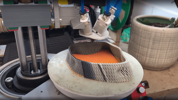
trick is to use the same weight maps and simply map colours to blender text blocks which are injected into the gcode at export time. These gcode blocks can be used swap tool heads or extruders, enabling blending of multiple filament colours or types in the same object.

Some nice examples of such printing manipulation can be seen on [Heinz’s] instagram page for the project. So, going back to the hardware again, the first video embedded below shows the ‘dual disk polar printer’ fitted with a crazy five-extruders-into-one-nozzle mixing hotend setup, which should be capable of full CMYK colour mixing and some. The second video below shows an interesting by-product of the wide horizontal motion range of the machine, that the whole printing area can be shifted to a nozzle at the other end of the gantry. This enables a novel way to switch extruders, by just moving the whole bed and print under the nozzle of interest! One final observation — is that of the print surface — it does look rather like they’re printing direct onto a slab of marble, which I think is the first time we’ve seen that.

Interesting printer designs are being worked on a lot these days, here’s a really nice 5-axis prusa i3 hack, and if you want to stay in the cartesian world, but your desktop machine is just too small, then you can always supersize it.

Continue reading “Texture Map GCode Directly In Blender With NozzleBoss”