It started with [CHORL] making a promise to himself regarding constructing a new combat robot: no spending of money on the new robot.
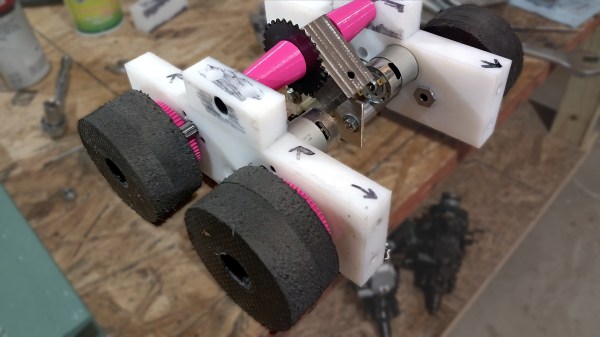
That rule was violated (but only a little) by making his robot’s wheels out of EVA kneeling pads. EVA (Ethylene-Vinyl Acetate) is a closed-cell foam that makes for durable yoga mats, kneeling pads, and products of a similar nature. [CHORL] found a way to turn them into light but serviceable wheels for his robot: the Susquehanna Boxcar.
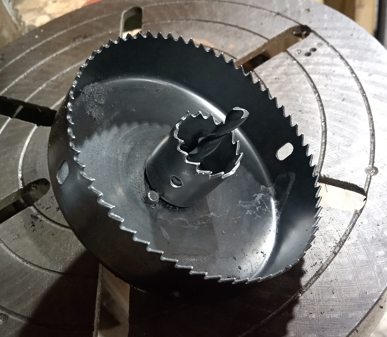
Here’s how the wheels were made: [CHORL] began with two hole saws. Nesting a smaller hole saw into a larger one by putting both on the same arbor created a saw with two holes, both of which were centered with respect to one another. The only problem was that this hole saw was not actually deep enough to cut completely through the thick foam. Luckily, cutting roughly halfway through on one side, then flipping the sheet over and cutting through from the other side was a good workaround. That took care of turning the thick foam sheet into round wheels.
A 3D-printed part served as a wheel hub as well as gear for the drivetrain. We want to call attention to the clever method of reinforcing the connection between the parts. [CHORL] didn’t want to just glue the geared hub directly to the surface of the foam wheel, because he suspected it might separate under stress. To address this, he designed six slots into the hub, cut matching slots into the foam wheel, and inserted six spline-like reinforcements in the form of some ABS strips he had on hand. Gluing it all together with E-6000 and leaving it to cure overnight under a weight resulted in a geared wheel assembly that [CHORL] judged to be about as round and rigid as a wheel should be, so the robot had a solution for nice light wheels that were, above all, cheap!


Lots of robots need wheels, and unsurprisingly, DIY solutions are common projects. [CHORL]’s approach here looks pretty scalable, as long as one can cut some accurate holes.
Interested in knowing more about the robot these wheels are destined for? [CHORL]’s still working on the Susquehanna Boxcar, but it’s almost done, and you can read a bit more about it (and see a few more pictures) here.