Faulty Electrolytic Caps Don’t Always Look Bad

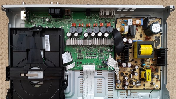
Old electrolytic capacitors are notorious for not working like they used to, but what exactly does a bad capacitor look like, and what kinds of problems can it cause? Usually bad caps leak or bulge, but not always. In [Zak Kemble]’s case, a bad cap caused his Samsung HT-C460 Home Cinema System to simply display “PROT” then turn itself off. Luckily, replacing the troublesome cap fixed everything, but finding the problem in the first place wasn’t quite so straightforward. A visual inspection of the device, shown open in the photo above, didn’t reveal any obvious problems. None of the capacitors looked anything out of the ordinary, but one of them turned out to be the problem anyway.

The output cap had developed an internal short, but visually looked fine.

The first identifiable issue was discovering that the -5 V supply was only outputting about -0.5 V, and there was a 6 V drop across two small 0805-sized resistors, evidence that something was sinking far more current than it should.

Testing revealed that the -5 V regulator wasn’t malfunctioning, and by process of elimination [Zak] finally removed the 470 uF output capacitor on the -5 V output, and the problem disappeared! Inspecting the capacitor revealed no outward sign of malfunction, but it had developed an internal short. [Zak] replaced the faulty cap (and replaced the others just to be safe) and is now looking forward to getting years more of use out of his home cinema system.

When a PSU gives up the ghost, bad capacitors are almost always to blame, but we’ve seen before that it’s not always easy to figure out which ones are bad. One thing that helped [Zak] plenty in his troubleshooting is finding a full schematic of the power supply, just by doing a search for the part number he found on it. A good reminder that it’s always worth throwing a part number into a search engine; you might get lucky!

PNG Image Decoding Library Does It With Minimal RAM

Want to display a PNG file on a display attached to an Arduino or other microcontroller board? You’ll want to look at [Larry Bank]’s PNGdec, the Arduino-friendly PNG decoder library which makes it much easier to work with PNG files on your chosen microcontroller.

The PNG image format supports useful features like lossless compression, and was generally developed as an improved (and non-patented) alternative to GIF files. So far so great, but it turns out that decoding PNG files on a microcontroller is a challenge due to the limited amount of memory compared to desktop machines. When the PNG specification was developed in the 90s, computers easily had megabytes of memory to work with, but microcontrollers tend to have memory measured in kilobytes, and lack high-level memory management. [Larry]’s library addresses these issues.

PNGdec is self-contained and free from external dependencies, and also has some features to make converting pixel formats for different display types easy. It will run on any microcontroller that can spare at least 48 K of RAM, so if that sounds useful then check out the GitHub repository for code and examples.

We’ve seen [Larry]’s wonderful work before on optimizing GIF playback as well as rapid JPEG decoding, and these libraries have increasing relevance as hobbyists continue to see small LCD and OLED-based displays become ever more accessible and affordable.

[PNG logo: PNG Home Site]

Big 3D-Printed Lamp Tries Some New Features

In lamp design, bulbs are usually given generous clearances because they get hot during use. LED bulbs however give off comparatively little heat, which opens a few new doors. [Mark Rehorst] created this huge 3D printed lamp, made with his custom 3D printer and a hefty 1 mm diameter nozzle, and the resulting device not only looks great, but shows off a few neat design features.

The LED filament bulb doesn’t give off much heat, so a PETG partial shade mounted directly to the bulb works fine.

[Mark] printed a partial shade in PETG that is made to sit directly on the bulb itself. The back of the shade is open, allowing light to spill out from behind while the front of the bulb is shielded, making it easier on the eyes. The result is pretty nifty, as you can see here. It sits in the center of the 600 mm tall lamp, which takes up most of the build volume of his self-made CoreXY-based printer, the UMMD.

The LED filament strands in this style of bulb are pretty neat in their own way, and some of you may remember that when they first became available as separate components, no time was lost in finding out what made them tick.

High-Tech Paperweight Shows Off Working 60s-era Thin-Film Electronics

[Ken Shirriff]’s analysis of a fascinating high-tech paperweight created by GE at the height of the space race is as informative as it is fun to look at. This device was created to show off GE’s thin-film electronics technology, and while it’s attractive enough on its own, there’s an added feature: as soon as the paperweight is picked up, it begins emitting a satellite-like rhythmic beep. It is very well-made, and was doubtlessly an impressive novelty for its time. As usual, [Ken] dives into what exactly makes it tick, and shares important history along the way.

Thin-film module with labels, thanks to [Ken]’s vintage electronics detective work. Click to enlarge.
In the clear area of the paperweight is a thin-film circuit, accompanied by a model of an early satellite. The module implements a flip-flop, and the flat conductors connect it to some additional components inside the compartment on the left, which contains a power supply and the necessary parts to create the beeps when it is picked up.

Thin-film electronics reduced the need for individual components by depositing material onto a substrate to form things like resistors and capacitors. The resulting weight and space savings could be considerable, and close-ups of the thin film module sure look like a precursor to integrated circuits. The inside of the left compartment contains a tilt switch, a battery, a vintage earphone acting as a small speaker, and a small block of components connected to the thin-film module. This block contains two oscillators made with unijunction transistors (UJTs); one to create the beep, and one to control each beep’s duration. The construction and overall design of the device is easily recognizable, although some of the parts are now obsolete.

If you’d like a bit more detail on exactly how this device worked, including circuit diagrams and historical context, be sure to click that first link, and pay attention to the notes and references at the end. One other thing that’s clear is that functional electronics embedded in clear plastic shapes simply never go out of style.

Skin-Mounted Wearable Bend Sensor Gets Close And Personal

[Mikst] has been working on wearable electronics and sensors for a long time, and shared the results of a different kind of bend sensor that fits directly onto the skin. It’s true that this kind of sensor design isn’t re-usable, but it is also very simple and inexpensive. It’s just a proof of concept right now, but we could see it or some of the other ideas [Mikst] tries, used in niche wearable applications where space is critical, like cosplay.

At its heart the sensor is made from two strands of conductive thread and a small strip of stretchy, conductive fabric common in wearable e-textiles. It is stuck directly to the skin using a transparent, non-woven medical adhesive dressing that is particularly good at conforming to contoured areas of the body. In this case, it is used to stick the stretchy piece of conductive fabric directly onto [Mikst]’s knuckle, where it responds to even small movements. You can watch a multimeter measuring the resistance changes in the video, embedded below.

We’ve seen [Mikst]’s work before in finding unusual solutions to e-textile problems, such as a three-conductor pivoting connection used to mount a wearable hall effect sensor.

Continue reading “Skin-Mounted Wearable Bend Sensor Gets Close And Personal”

USB Power Bank’s Auto-Off Becomes Useful Feature In Garage Door Remote

For devices that are destined for momentary and infrequent use as well as battery power, some kind of power saving is pretty much a required feature. For example, when [PJ Allen] turned two ESP8266-based NodeMCU development boards into a replacement wireless remote garage door opener, a handy USB power bank ended up serving as a bit of a cheat when migrating the remote away from the workbench. Instead of moving the board from USB to battery power and implementing some kind of sleep mode or auto-off, [PJ Allen] simply plugged in a USB power bank and let it do all the work.

This is how the feature works: some USB power banks turn themselves off unless they detect a meaningful current draw. That means that if the power bank is charging a phone, it stays on, but if it’s only lighting up a few LEDs, it’ll turn itself off. This feature can be a frustrating one, but [PJ Allen] realized that it could actually be useful for a device like his garage door remote. Turning on the power bank delivers 5 V to the NodeMCU board and allows it to work, but after about fifteen seconds, the power bank turns itself off. Sure, strapping a power bank to the remote makes the whole thing bigger than it needs to be, but it’s a pretty clever use of the minimum load as an effortless auto-off feature.

The NodeMCU boards in [PJ Allen]’s DIY remote use ESP-NOW for their wireless communications, a nifty connectionless protocol from Espressif that we’ve seen used in other projects as well, such as this ESP32-based walkie-talkie.

A New Spin On Empty Filament Spools For Part Storage

Empty spools from 3D printer filament are the kind of thing that begs to be repurposed, and one option is [3d-printy]’s vertical filament spool parts drawer design. The way this solution works is by using the spool to hold twelve vaguely pie-shaped drawers that can be individually unlocked and removed entirely, which makes accessing their contents (or dumping them out) much easier. This method requires the spools to be oriented vertically, so it ends up handling a bit like a Rolodex.

One downside of the design is that it requires two inserts to be installed on the inside of the spool walls, which act as guide rails and lock points for the drawers. Another is that managing a vertical spool can be a bit awkward, given its lack of flat surfaces. Happily, there is an option for a matching stand that not only provides a flat base, but keeps any accidentally-unlocked drawers from falling out and spilling their contents.

The project files are OpenSCAD files, which allows easy customization for different spool manufacturers and dimensions, and [3d-printy] provides measurements for some common ones. Another nice element of this design is that no single part uses more than 30 grams of filament, which makes printing them an attractive way to use up the last bits of filament rolls.

We’ve seen drawer-style storage for filament spools before, but haven’t seen a design quite like this one before. Watch an overview of the drawer design as well as the spool holders in the videos, embedded below.

Continue reading “A New Spin On Empty Filament Spools For Part Storage”