A Voltage Regulator Before Electronics

Did you ever wonder how the mechanical voltage regulator — that big black box wired up to the generator on a car from the ’60s or before — worked? [Jonelsonster] has some answers.

For most people in 2026 an old car perhaps means one from the 20th century, now that vehicles from the 1990s and 2000s  have become the beloved jalopies of sallow youths with a liking for older cars and a low budget. But even a 1990s vehicle is modern in terms of its technology, because a computer controls the show. It has electronic fuel injection (EFI), anti-lock braking system (ABS), closed loop emissions control, and the like.

Go back in time to the 1970s, and you’ll find minimal electronics in the average car. The ABS is gone, and the closest thing you might find to EFI is an electronic ignition where the points in the distributor have been replaced with a simple transistor. Perhaps an electronic voltage regulator on the alternator. Much earlier than that and everything was mechanical, be that the ignition, or that regulator.

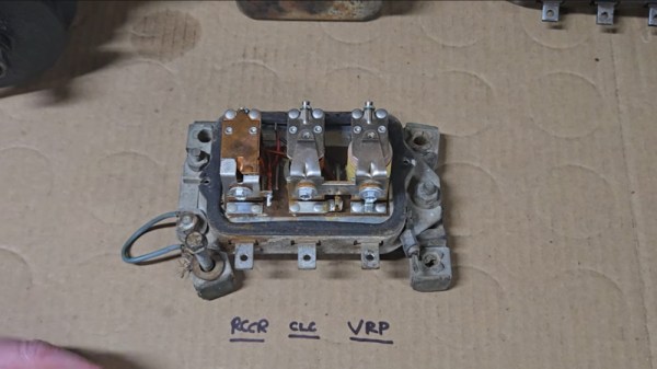
The video below the break has a pair of units, it seems from 1940s tractors. They would have had a DC generator, a spinning coil with a commutator and brushes, in a magnetic field provided by another coil. These things weren’t particularly powerful by today’s standards and sometimes their charging could be a little lackluster, but they did work. We get to see how, as he lifts the lid off to reveal what look like a set of relays.

We’re shown the functions of each of the three coils with the aid of a lab power supply; we have a reverse current relay that disconnects the generator if the battery tries to power it, an over-current relay that disconnects the field coil if the current is too high, and an over-voltage relay that does the same for voltage. The regulating comes down to the magnetic characteristics, and while it’s crude, it does the job.

We remember European devices with two coils and no field terminal, but the principle is the same. There is never a dull moment when you own an all mechanical car.

Continue reading “A Voltage Regulator Before Electronics”

The Shockley 4-Layer Diode In 2026

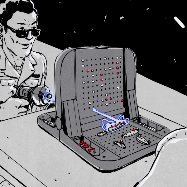
The physicist William Shockley is perhaps today best known for three things: his role in the invention of the transistor, his calamitous management of Shockley Semiconductor which led to a mass defection of employees and precipitated the birth of the Silicon Valley we know, and his later descent into promoting eugenics. This was not the sum of his work though, and [David Prutchi] has been experimenting with a now-mostly-forgotten device that bears the Shockley name (PDF), after finding one used in an early heart pacemaker circuit.  His findings are both comprehensive and fascinating.

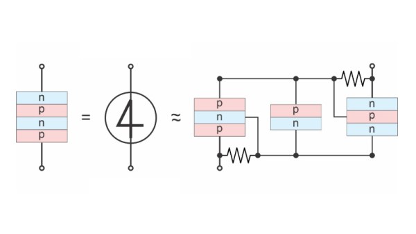
The Shockley diode, or 4-layer diode as it later became known, is as its name suggests a two terminal device with a 4-layer NPNP structure. It can be modeled as a pair of complementary transistors in parallel with a reverse biased diode, and the avalanche breakdown characteristics of that diode when a particular voltage is applied to it provide the impetus to turn on the two transistors. This makes it a voltage controlled switch, that activates when the voltage across it reaches that value.

The PDF linked above goes into the Shockley diode applications, and in them we find a range of relaxation oscillators, switches, and logic circuits. The oscillators in particular could be made with the barest minimum of components, important in a time when each semiconductor device could be very expensive. It may have faded into obscurity as it was superseded by more versatile 4-layer devices such as the PUJT or silicon-controlled switch and then integrated circuits, but he makes the point that its thyristor cousin is still very much with us.

This appears to be the first time we’ve featured a 4-layer diode, but we’ve certainly covered the genesis of the transistor in the past.

OS/2 Never Went Away. Its Successor Has Received An Update

ArcaOS is an operating system you might not have heard of, but you will recognize it when we tell you that it’s the direct descendant of IBM’s OS/2. It’s just received a major update, and delivers this persuasive argument for its uptake:

“How about a commercial operating system which doesn’t spy on you, does not report your online activity to anyone, and gives you complete freedom to choose the applications you want to use, however you want to use them?”

We’re guessing that a higher-than-average number of Hackaday readers use open-source operating systems, but in a world in which the commercial OS everyone loves to hate is ever more turning the Play button into the Pay button, we have to admit that’s attractive if you pay for your software.

This update, version 5.1.2, brings support for the very latest UEFI systems to the table, keeping the platform alive in a manner we’d never have guessed would happen back in the 1990s. It’s true it’s a 32-bit system rather than 64-bit, and you’d be unlikely to buy it for your high-end gaming machine, but we remember OS/2 Warp back in the day as being very nice indeed and particularly stable. We’re interested enough to have put in a cheeky request for a review ISO, so should that come off we’d love to give it the Jenny’s Daily Drivers treatment.

ArcaOS has been mentioned here before. Do any of our readers encounter it in your daily lives? We’d love to hear in the comments.

How Would A Field Sequential Home Computer Have Worked?

The early history of colour TV had several false starts, of which perhaps one of the most interesting might-have-beens was the CBS field-sequential system. This was a rival to the nascent system which would become NTSC, which instead of encoding red, green, and blue all at once for each pixel, made sequential frames carry them.

The Korean war stopped colour TV development for its duration in the early 1950s, and by the end of hostilities NTSC had matured into what we know today, so field-sequential colour became a historical footnote. But what if it had survived? [Nicole Express] takes into this alternative history, with a look at how a field-sequential 8-bit home computer might have worked.

The CBS system had a much higher line frequency in order to squeeze in those extra frames without lowering the overall frame rate, so given the clock speeds of the 8-bit era it rapidly becomes obvious that a field-sequential computer would be restricted to a lower pixel resolution than its NTSC cousin. The fantasy computer discussed leans heavily on the Apple II, and we explore in depth the clock scheme of that machine.

While it would have been possible with the faster memory chips of the day to achieve a higher resolution, the conclusion is that the processor itself wasn’t up to matching the required speed. So the field-sequential computer would end up with wide pixels. After a look at a Breakout clone and how a field-sequential Atari 2600 might have worked, there’s a conclusion that field-sequential 8-bit machines would not be as practical as their NTSC cousins. From where we’re sitting we’d expect them to have used dedicated field-sequential CRT controller chips to take away some of the heartache, but such fantasy silicon really is pushing the boundaries.

Meanwhile, while field-sequential broadcast TV never made it, we do have field-sequential TV here in 2026, in the form of DLP projectors. We’ve seen their spinning filter disks in a project or two.


1950 CBS color logo: Archive.org, CC0.

A Radio Power Amplifier For Not A Lot

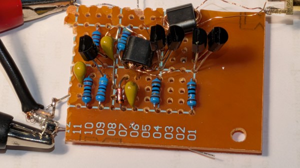
When building a radio transmitter, unless it’s a very small one indeed, there’s a need for an amplifier before the antenna. This is usually referred to as the power amplifier, or PA. How big your PA is depends on your idea of power, but at the lower end of the power scale a PA can be quite modest. QRP, as lowe power radio is referred to, has a transmit power in the miliwatts or single figure watts. [Guido] is here with a QRP PA that delivers about a watt from 1 to 30 MHz, is made from readily available parts, and costs very little.

Inspired by a circuit from [Harry Lythall], the prototype is built on a piece of stripboard. It’s getting away with using those cheap transistors without heatsinking because it’s a class C design. In other words, it’s in no way linear; instead it’s efficient, but creates harmonics and can’t be used for all modes of transmission. This PA will need a low-pass filter to avoid spraying the airwaves with spurious emissions, and on the bands it’s designed for, is for CW, or Morse, only.

We like it though, as it’s proof that building radios can still be done without a large bank balance. Meanwhile if the world of QRP interests you, it’s something we have explored in the past.

A Rotary Dial The 3D Printed Way

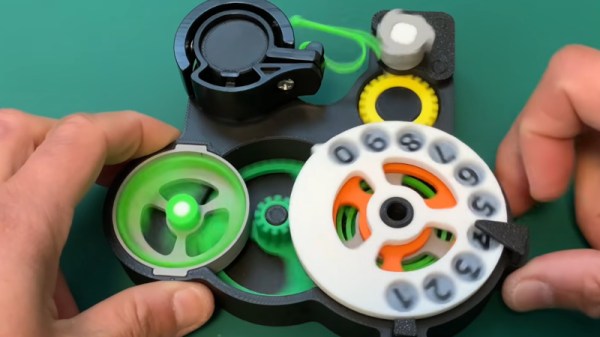
There’s a meme which may have a basis in truth, of a teenager left clueless when presented with a rotary telephone. The dial, in reality a mechanical pulse chain generator, was once ubiquitous enough that having one in your parts bin was anything but unusual. If you’re curious about their inner workings in 2026 though, you may be out of luck. Never fear though, because [Moeya 3D Designs] is here with a fully 3D printed version. It’s not as compact as the original, but it’s all there.

If you’re not put off by the anime-style Japanese voice over on the video below the break and you can enable subtitles for your language, you get the full explanation. There’s a ratchet and spring on the dial, which when released drives a gear train that ends in a cam that would operate a switch for the pulses. Another set of gears drives a very neatly designed centrifugal speed governor, and we see the effect immediately when it is removed. We’re not sure who will go for this project, but we surely like it.

There are two videos below the break, with the dial shown off in the first and the design process in the second. Meanwhile we’ve talked in the past about the networks behind the dials. Continue reading “A Rotary Dial The 3D Printed Way”

Power Control For A Busy Workbench

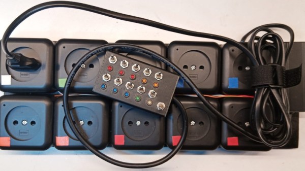
Who among us does not have a plethora of mains-powered devices on their workbench, and a consequent mess of power strips to run them all? [Jeroen Brinkman] made his more controllable with a multi-way switch box.

At first sight it’s a bank of toggle switches, one for each socket. But this is far more than a wiring job, because of course there are a couple of microcontrollers involved, and each of those switches ultimately controls a relay. There are also status LEDs for each socket, and a master switch to bring them all down. Arduino code is provided, so you can build one too if you want to.

We like the idea of a handy power strip controller, and especially the master switch with the inherent state memory provided by the switches. This could find a home on a Hackaday bench, and we suspect on many others too. It’s by no means the first power strip with brains we’ve seen, but most others have been aimed at the home instead.