The World’s Thinnest Raspberry Pi 3

We’ve become used to readily available single board computers of significant power in form factors that would have seemed impossibly small only a few years ago. But even with a board the size of a credit card such as a Raspberry Pi, there are still moments when the available space is just too small to fit the computer.

The solution resorted to by enterprising hardware hackers is often to remove extraneous components from the board. If there is no need for a full-size USB port or an Ethernet jack, for example, they can safely be taken away. And since sometimes these attempts result in the unintended destruction of the board, yonder pirates at Pimoroni have taken viewers of their Bilge Tank series of videos through the procedure, creating in the process what they describe as “The World’s Thinnest Raspberry Pi 3“.

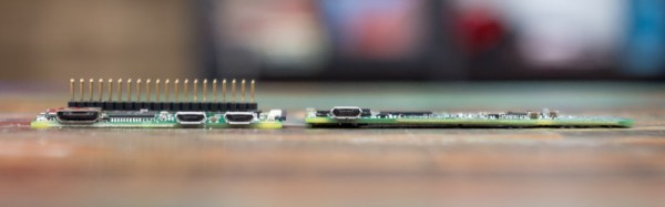
The USB and Ethernet ports, as large through-hole components, were the easiest to tackle. Some snipping and snapping removed the tinware and plastic, then the remains could be hand-desoldered. The GPIO pins resisted attempts to remove their plastic for easy desoldering, so for them they had to resort to a hot air gun. Then for the remaining camera, HDMI, and display ports the only option was hot air. Some cleaning up with desoldering braid, and they had their super-thin Pi. They weren’t quite done though, they then took the reader through modifying a Raspbian Lite distribution to deactivate support those components that have been removed. This has the handy effect not only of freeing up computer resources, it also saves some power consumption.

You might point out that they could have just used a Pi Zero, which with its SD card on the top surface is even a little bit thinner. And aside from the question of extra computing power, you’d be right. But their point is valid, that people are doing this and not always achieving a good result, so their presenting it as a HOWTO is a useful contribution. We suspect that a super-thin Pi 3 will still require attention to heat management though.

Take a look at the video, we’ve put it below the break.

Continue reading “The World’s Thinnest Raspberry Pi 3”

Retrotechtacular: Information From The Days When Colour TV Was New

By the time colour TV came to the United Kingdom, it was old news to Americans. Most of the viewing public on the Western side of the Atlantic had had the opportunity to see more than black-and-white images for years when in 1967 the BBC started transmitting its first colour channel, BBC2.

For Americans and continental Europeans, the arrival of colour TV had been an incremental process, in which the colour subcarrier had been added to their existing transmission standard. Marketed as “compatible color” to Americans, this ensured that their existing black-and-white TV sets had no need for replacement as the new transmissions started.

The United Kingdom by contrast had been one of the first countries in the world to adopt a television standard in the 1930s, so its VHF 405-line positive-modulation black-and-white services stood alone and looked extremely dated three decades later. The BBC had performed experiments using modified round-CRT American sets to test the feasibility of inserting an NTSC colour subcarrier into a 405-line signal, but had eventually admitted defeat and opted for the Continental 625-line system with the German PAL colour encoding. This delivered colour TV at visibly better quality than the American NTSC system, but at the expense of a 15-year process of switching off all 405-line transmitters, replacing all 405-line sets, and installing new antennas for all viewers for the new UHF transmissions.

Such a significant upgrade must have placed a burden upon the TV repair and maintenance trade, because as part of the roll-out of the new standard the BBC produced and transmitted a series of short instructional animated films about the unfamiliar technology, which we’ve placed below the break. The engineer is taken through the signal problems affecting UHF transmissions, during which we’re reminded just how narrow bandwidth those early UHF Yagis must have been, then we are introduced to the shadowmask tube and all its faults. The dreaded convergence is introduced, as these were the days before precision pre-aligned CRTs, and we briefly see an early version of the iconic Test Card F. Finally we are shown the basic procedure for achieving the correct white balance. There is a passing reference to dual-standard sets, as if convergence for colour transmissions wasn’t enough of a nightmare a lot of the early colour sets incorporated a bank of switches on their PCB to select 405-line or 625-line modes. The hapless engineer would have to set up the convergence for both signals, something that must have tried their patience.

The final sequence looks at the hand-over of the new set to the customer. In an era in which we are used to consumer electronics with fantastic reliability we would not be happy at all with a PAL set from 1967. They were as new to the manufacturers as they were to the consumers, so the first generation of appliances could hardly have been described as reliable. The smiling woman in the animated film would certainly have needed to call the engineer again more than once to fix her new status symbol.

Continue reading “Retrotechtacular: Information From The Days When Colour TV Was New”

The Things Network Sets 702 Km Distance Record For LoRaWAN

Many of us will have at some time over the last couple of years bought a LoRaWAN module or two to evaluate the low power freely accessible wireless networking technology. Some have produced exciting and innovative projects using them while maybe the rest of us still have them on our benches as reminders of projects half-completed.

If your LoRaWAN deployment made it on-air, you’ll be familiar with the range that can be expected. A mile or two with little omnidirectional antennas if you are lucky. A few more miles if you reach for something with a bit of directionality. Add some elevation, and range increases.

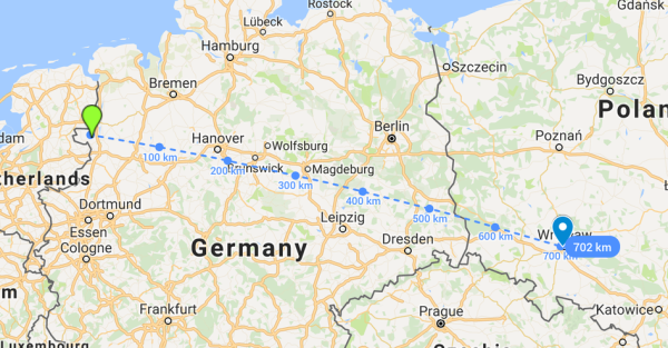
A couple of weeks ago at an alternative society festival in the Netherlands, a balloon was launched with a LoRaWAN payload on board that was later found to have made what is believed to be a new distance record for successful reception of a LoRaWAN packet. While the balloon was at an altitude of 38.772 km (about 127204.7 feet) somewhere close to the border between Germany and the Netherlands, it was spotted by a The Things Network node in Wroclaw, Poland, at a distance of 702.676km, or about 436 miles. The Things Network is an open source, community driven effort that has built a worldwide LoRaWAN network.

Of course, a free-space distance record for a balloon near the edge of space might sound very cool and all that, but it’s not going to be of much relevance when you are wrestling with the challenge of getting sensor data through suburbia. But it does provide an interesting demonstration of the capabilities of LoRaWAN over some other similar technologies, if a 25mW (14dBm) transmitter can successfully send a packet over that distance then perhaps it might be your best choice in the urban jungle.

If you’re curious about LoRaWAN, you might want to start closer to home and sniff for local activity.

If You’re Going To Make A Model Engine, You Might As Well Make It A Merlin

It has been remarked before in more than one Hackaday post, that here are many communities like our own that exist in isolation and contain within them an astonishing level of hardware and engineering ability. We simply don’t see all the work done by the more engineering-driven and less accessory-driven end of the car modification scene, for example, because by and large we do not move in the same circles as them.

One such community in which projects displaying incredible levels of skill are the norm is the model making world. We may all have glued together a plastic kit of a Spitfire or a Mustang in our youth, but at the opposite end of the dial when it comes to models you will find craftsmanship that goes well beyond that you’d find in many high-end machine shops.

A project that demonstrates this in spades is [mayhugh1]’s quarter-scale model of a vintage Rolls-Royce Merlin V12 piston aero engine. This was the power plant that you would have found in many iconic Allied aircraft of the WW2 era, including the real-life Spitfires and all but the earliest of those Mustangs. And what makes the quarter-scale Merlin just that little bit more special, is that it runs. Just add fuel.

The build took place over a few years and many pages of a forum thread, and includes multiple blow-by-blow accounts, photos, and videos. It started with a set of commercial castings for the engine block, but their finishing and the manufacture of all other engine parts is done in the shop. In the final page or so we see the video we’ve placed below the break, of the finished engine in a test frame being run up on the bench, with a somewhat frightening unguarded airscrew attached to its front and waiting to decapitate an unwary cameraman. Sit down with a cup of your favourite beverage, and read the build from start to finish. We don’t think you’ll be disappointed.

Continue reading “If You’re Going To Make A Model Engine, You Might As Well Make It A Merlin”

Scribble Your Way To Quick Printed Circuit Boards

There are a variety of techniques employed by electronic constructors seeking the convenience of a printed circuit board without the inconvenience of making a printed circuit board. Dead bug style construction in which the components float on a spiders-web of soldered leads above a ground plane is one, Manhattan style construction in which pads made from small cut squares of bare copper-clad PCB are glued on top of a groundplane is another.

[Freestate QRP] has another take on this type of electronics, with what he calls “Scribble style” construction. He cuts away copper from bare board to create pads and rudimentary tracks, and for him the magic ingredient comes from his choice of an engineer’s scribe to do the job. This is where the “scribble” comes from, creating a pad is as simple as drawing it with the scribe.

Of course, this technique is not entirely new, constructors have been doing this type of work for years with Dremel tools, hand engraving tools, and similar. If you’ve ever tried to do it with a knife or scalpel you will know that it’s hardly an easy task with those hand tools so the prospect of another one doing a better job is rather interesting. He’s ready and able to demonstrate it in action, showing us a couple of RF circuits using the technique.

Have you tried this technique, or one like it? How did you get on, tell us in the comments. Meanwhile, you might like to read our own [Dan Maloney]’s look at dead bug and Manhattan construction.

A Great Guide To Software PLLs

There are some things that you think you know quite well because you learned them in your youth and you understand their principles of operation. Then along comes a link in your morning feed that reminds you of the limits of your knowledge, and you realize that there is a whole new level of understanding to be reached.

Take Phase Locked Loops (PLLs) for example. You learn how they work, you use them for frequency synthesis, and you know they can do other things like recover noisy clock lines and do FM demodulation. But then you read [Paul Lutus’] Understanding Phase-Locked Loops page, and a whole new vista opens.

He’s discussing PLLs in the context of software, as part of a weather fax decoder project, and this allows a perspective that was unavailable to those of us who learned about them through the medium of hardware such as the venerable 4046 CMOS chip. We can easily look at different PLLs with varying parameters, for example their use with a narrowband loop filter to retrieve signals buried in the noise, all through some straightforward code tweaks rather than extensive circuitry. It’s a page that’s a few years old now, but resources like this one do not age.

If PLLs are entirely new to you then you need to reat last year’s excellent PLL primer by Hackaday’s own [Al Williams].

[via Hacker News]

[PLL diagram: Chetvorno CC0]

Attack Some Wireless Devices With A Raspberry Pi And An RTL-SDR

If you own one of the ubiquitous RTL-SDR software defined radio receivers derived from a USB digital TV receiver, one of the first things you may have done with it was to snoop on wide frequency bands using the waterfall view present in most SDR software. Since the VHF and UHF bands the RTL covers are sometimes a little devoid of signals, chances are you homed in upon one of the ISM bands as used by plenty of inexpensive wireless devices for all sorts of mundane control tasks. Unless you reside in the depths of the wilderness, ISM band sniffing will show a continuous procession of chirps; short bursts of digital data. It is surprising, the number of radio-controlled devices you weren’t aware were in your surroundings.

Some of these devices, such as car security keys, are protected by rolling encryption schemes to deter would-be attackers. But many of the more harmless devices simply send a command in the open without the barest of encryption. The folks at RTL-SDR.com put up a guide to recording these open data bursts on a Raspberry Pi and playing them back by transmitting them from the Pi itself.

It’s not the most refined of attack because all it does is take the recorded file and retransmit it with the [F5OEO] RPiTX software. But they do demonstrate it in action with a wireless lightbulb, a door bell, a wireless relay, and a remote-controlled switched socket. Since the data in question is transmitted as OOK, or on-off keying, the RPiTX AM mode stands in for the transmitter.

You can see it in action in the video below the break. Now, have you investigated the ISM band chirps in your locality?

Continue reading “Attack Some Wireless Devices With A Raspberry Pi And An RTL-SDR”