A Very Tidy Circular Saw Bench

If your parents had a workshop as you grew up, the chances are it harbored some tools you came to know and love as you used them for your formative projects. Our reader [Joerg]’s father for instance has a circular saw bench that [Joerg] sorely misses, now living over 500km away. Our subject today is his response to this problem, now needing to cut aluminium he set about creating a  saw bench of his own, and the result is a rather nice build.

table-saw
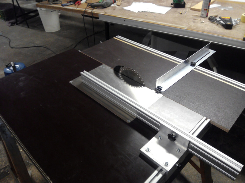
He put together a variety of CAD models to formulate his ideas, and arrived at a structure in 18mm waterproof plywood with moving table linear bearings. The saw blade itself was mounted on a 5mm aluminum plate, though he doesn’t tell us what motor it uses. All the wooden parts came from a single sheet of plywood, and the result is a very tidy creation indeed.

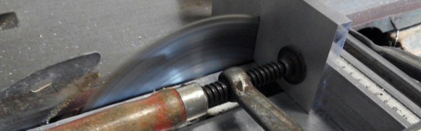
Power saws are among the more hazardous tools in your workshop arsenal, whatever their type. If this was a commercial saw it would probably have a guard over the top of its blade, but even without that its sturdy construction and relatively low profile blade make this one stand above some of the more basic home-made saws we’ve seen. Building a power saw is something you have to take seriously.

We’ve featured quite a few home-made saws over the years. At least one other large table saw, a rather powerful but surprisingly tiny saw bench, this scroll saw using a sewing machine mechanism, or how about this simple jigsaw table?

Emulating A Remote Control Ceiling Fan Transmitter In An FPGA

[Joel] has a remote control ceiling fan. It’s nothing special, the controller has a low-power 350MHz transmitter and a Holtek encoder to send commands by keying the transmitter’s output. Desiring something a little better, he set about reverse engineering the device’s protocol and implementing it on a Lattice iCE40 FPGA.

To decode the device’s packets he reached for his RTL-SDR receiver and took a look at it in software. GQRX confirmed the presence of the carrier and allowed him to record a raw I/Q file, which he could then supply to Inspectrum to analyse the packet structure. He found it to be a simple on-off keying scheme, with bits expressed through differing pulse widths. He was then able to create a Gnu Radio project to read and decode them in real time.

Emulating the transmitter was then a fairly straightforward process of generating a 350MHz clock using the on-board PLL and gating it with his generated data stream to provide modulation. The result was able to control his fan with a short wire antenna, indeed he was worried that it might also be doing so for other similar fans in his apartment complex. You can take a look at his source code on GitHub if you would like to try something similar.

It’s worth pointing out that a transmitter like this will radiate a significant amount of harmonics at multiples of its base frequency, and thus without a filter on its output is likely to cause interference. It will also be breaking all the rules set out by whoever the spectrum regulator is where you live, despite its low power. However it’s an interesting project to read, with its reverse engineering and slightly novel use of an FPGA.

Wireless remote hacking seems to be a favorite pastime here in the Hackaday community. We’ve had 2.4GHz hacks and plenty of wireless mains outlet hacks.

IPhone Polarizing Camera Solves Filter Orientation Problem Using Flash

One of last year’s Hackaday Prize finalists was the DOLPi, [Dave Prutchi]’s polarimetric camera which used an LCD sheet from a welder’s mask placed in front of a Raspberry Pi camera. Multiple images were taken by the DOLPi at different polarizations and used to compute images designed to show the polarization of the light in each pixel and convey it to the viewer through color.

The polarizer and phototransistor taped to the iPhone.

[Dave] wrote to tip us off about [Paul Wallace]’s take on the same idea, a DOLPi-inspired polarimetric camera using an iPhone with an ingenious solution to the problem of calibrating the device to the correct polarization angle for each image that does not require any electrical connection between phone and camera hardware. [Paul]’s camera is calibrated using the iPhone’s flash. The light coming from the flash through the LCD is measured by a phototransistor and Arduino Mini which sets the LCD to the correct polarization. The whole setup is taped to the back of the iPhone, though we suspect a 3D-printed holder could be made without too many problems. He provides full details as well as code for the iPhone app that controls the camera and computes the images on his blog post.

We covered the DOLPi in detail last year as part of our 2015 Hackaday Prize finalist coverage. You can also find its page on Hackaday.io, and [Dave]’s own write-up on his blog.


Hackaday Prize Entry: A Minimal ATtiny Voltage And Frequency Counter

Sometimes when you build something it is because you have set out with a clear idea or specification in mind, but it’s not always that way. Take [kodera2t]’s project, he set out to master the ATtiny series of microcontrollers and started with simple LED flashers, but arrived eventually at something rather useful. An ATtiny10 DVM and DFM all-in-one with an i2c LCD display and a minimum of other components.

The DFM uses the ATtiny’s internal 16 bit timer, which has the convenient property of being able to be driven by an external clock. The frequency to be measured drives the timer, and the time it returns is compared to the system clock. It’s not the finest of frequency counters, depending as it does on the ATtiny’s clock rather than a calibrated crystal reference, but it does the job.

The results are shown in the video below, and all the code has been posted in his GitHub repository. We can see that there is the basis of a handy little instrument in this circuit, though with the price of cheap multimeters being so low even a circuit this minimal would struggle to compete on cost.

Continue reading “Hackaday Prize Entry: A Minimal ATtiny Voltage And Frequency Counter”

A Strandbeest Bicycle

“If you’re asking ‘why,’ you don’t get it.” So said [JP] when he told us about his strandbeest bicycle build. After all, who in their right mind would graft a complex multi-leg mechanical walking mechanism to the rear end of a perfectly good bicycle? But to expand on his sentiment, to not understand his creation is to miss the whole essence of our movement. Sometimes you just have to make something, because you can.

3D printed strandbeest bike proof of concept

If you aren’t familiar with the strandbeest, it is the creation of Dutch artist [Theo Jansen]. Complex skeletal walking machines powered by the wind, that in the case of [Jansen]’s machines autonomously roam the beaches of the Netherlands. Hence the name, from Dutch: “Beach beast”.

[JP]’s strandbeest bike came together over 8 months of hard work. It started with a conceptual CAD design and 3D print, and progressed through many iterations of fine-tuning the over 400 parts required to put four legs on the back of a bicycle frame. It’s an impressive achievement and it is fully rideable, though we suspect we won’t be seeing it at the Tour de France any time soon.

He’s posted several videos of the bike in action, you can see one of them below the break.

Continue reading “A Strandbeest Bicycle”

Die Photos Of A Runner’s RFID Chip

A mass participation sporting event such as a road race presents a significant problem for its record keepers. It would be impossible to have ten thousand timekeepers hovering over stopwatches at the finish line, so how do they record each runner’s time? The answer lies in an RFID chip attached to the inside of the bib each runner wears, which is read as the runner crosses the line to ensure that their time is recorded among the hundreds of other participants.

[Ken Shirriff] got his hands on a bib from San Francisco’s “Bay to Breakers” race, and set about a teardown to lay bare its secrets.

The foil antenna pattern.

Stripping away the foam covering of the RFID assembly revealed a foil antenna for the 860-960MHz UHF band with the tiny RFID chip at its centre. The antenna is interesting, it’s a rather simple wideband dipole folded over with what looks like a matching stub arrangement and an arrow device incorporated into the fold that is probably for aesthetic rather than practical purposes. He identified the chip as an Impinj Monza 4, whose data sheet contains reference designs for antennas we’d expect to deliver a better performance.

After some trial-by-fire epoxy removal the tiny chip was revealed and photographed. It’s a device of three parts, the power scavenging and analog radio section, the non-volatile memory that carries the payload, and a finite-state logic machine to do the work. This isn’t a proper processor, instead it contains only the logic required to do the one task of returning the payload.

He finishes off with a comparison photograph of the chip — which is about the size of a grain of salt — atop a 1980s 8051-series microcontroller to show both its tiny size and the density advancements achieved over those intervening decades.

Since RFID devices are becoming a ubiquitous part of everyday life it is interesting to learn more about them through teardowns like this one. The chip here is a bit different to those you’ll find in more mundane applications in that it uses a much higher frequency, we’d be interested to know the RF field strength required at the finish line to activate it. It would also be interesting to know how the system handles collisions, with many runners passing the reader at once there must be a lot of RFID chatter on the airwaves.

We’ve featured [Ken]’s work before, among many others in his reverse engineering of Clive Sinclair’s 1974 scientific calculator, and his explanation of the inner workings of the TL431 voltage reference. Though we’ve had many RFID projects on these pages, this appears to be the first teardown of one we’ve covered.

Reverse Engineering The OWON SDS7102 Oscilloscope

It is something of a rite of passage for an electronics enthusiast, the acquisition of a first oscilloscope. In decades past that usually meant a relatively modest instrument, maybe a 20MHz bandwidth and dual trace if you were lucky. Higher spec devices were eye-wateringly expensive monsters, not for the Common People.

We are fortunate that like most other areas of technology the world of test equipment has benefited in the last few years both from developments in digital technology and from the growth in Chinese manufacturing. If your first ‘scope is that second-hand 20MHz CRT you will probably secure it for pennies, and the first ‘scope you buy new will probably have a spec closer to those unattainable super-scopes of yesteryear. Gone is the CRT and timebase generator, in its place a TFT, system-on-chip, and super-fast A to D converter.

[Christer Weinigel] has just such an entry-level modern digital ‘scope, an OWON SDS7102. He comments that it’s got an impressive spec for its price, though the input is noisier than you’d expect on a more expensive device, and the software has one or two annoying bugs. Having owned it for a while, he’s now subjected it to a lengthy teardown and reverse engineer, and he’s posted his findings in a succession of blog posts.

[Christer]’s interest lay mainly in the OWON’s digital section, it seems there is already a substantial community paying attention to its analog front end. He’s deduced how its internals are connected, ported Linux to its Samsung SoC in the scope, succeeded in getting its peripherals working, and set to work programming the Xilinx FPGA that’s responsible for signal processing.

The series of posts is a fascinating read as a run through the process of reverse engineering , but he points out that it’s quite a lot of information. If you are just interested in how a cheap modern oscilloscope works, he says, he suggests reading his post in which he recaps on all its different components.

He also makes a plea for help, he’s no slouch on the ‘scope’s software but admits he’s a bit out of his depth on some aspects of the FPGA. If you’re an FPGA wizard with an interest in ‘scopes, he’d like to hear from you.

This isn’t the first time we’ve featured ‘scope reverse engineering here at Hackaday, though it may be more in-depth than others. In the past we’ve seen a Uni-T screen grab protocol laid bare, and an investigation of a Rigol 1054Z.