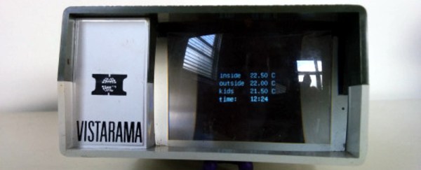
The Minima Is An All-Band HF Transceiver For Under $100

If you have ever browsed an amateur radio magazine you could be forgiven for receiving the impression that it is a pursuit exclusively for the wealthy. Wall-to-wall adverts for very large and shiny transceivers with hefty price tags abound, and every photograph of someone’s shack seems to sport a stack of them.

Of course, this is only part of the story. Amateur radio is and always has been an astonishingly diverse interest, and away from the world of shiny adverts you’ll find a lot of much more interesting devices. A lot of radio amateurs still design and build their own equipment, and the world of homebrew radio is forever producing new ideas.

One such project came to our attention recently, the Minima, an all-band HF SSB transceiver. It’s an interesting device for several reasons, it uses readily available components, it’s an impressively simple design, and it should cost under $100 to build. This might sound a little far-fetched, were it not from the bench of [Ashhar Farhan, VU2ESE], whose similarly minimalist BITX single band SSB transceiver set a new standard for accessible SSB construction a few years ago.

The circuit shares some similarities with the tried-and-tested BITX, using bi-directional amplifier building blocks. The mixers are now FETs rather than diodes, the intermediate frequency has moved from 9MHz to 20MHz, and the local oscillator is now an Arduino-controlled clock generator. The whole thing is designed to be built dead-bug-style if necessary, and two prototypes have been built. We’d expect this design to follow a similar evolution to the BITX, with the global community of radio amateurs contributing performance modifications, and no doubt with some kit suppliers producing PCBs and kits. We think this can only be a good thing, and look forward to covering some of the results.

We’ve featured [Ashhar]’s work here at Hackaday before, when we covered a BITX build. if you’re left wondering what this amateur radio business is all about, we suggest you have a read of [Bill Meara]’s guest post on the subject.

Thanks [Seebach] for the tip.

Safely Creating A Li-Ion Pack From Phone Cells

[Glen], at Maker Space Newcastle Upon Tyne, is refreshingly honest. As he puts it, he’s too cheap to buy a proper battery.

He needed a 1AH battery pack to power his quadcopter controller and FPV headset, and since inadequate discharge warnings had led him to damage lithium polymer cells with these devices, he wanted his pack to use lithium-ion cells. His requirements were that the cells be as cheap, lightweight, and small as possible, so to satisfy them he turned to a stack of mobile phone cells. Nokia BL-4U cells could be had for under a pound ($1.46) including delivery, so they certainly satisfied his requirement for cheapness.

It might seem a simple procedure, to put together a battery pack, and in terms of physical wiring it certainly is. But lithium-ion cells are not simply connected together in the way dry cells are, to avoid a significant fire risk they need to have the voltage of each individual cell monitored with a special balanced charger. Thus each cell junction needs to be brought out to another connector to the charger.

[Glen]’s write-up takes the reader through all the requirements of safe lithium-ion pack construction and charging, and is a useful read for any lithium-ion newbies. If nothing else it serves as a useful reminder that mobile phone cells can be surprisingly cheap.

Lithium cells have captured our attention before here at Hackaday. Our recent Hackaday Dictionary piece provides a comprehensive primer, we’ve featured another multi-cell build, and an interesting app note from Maxim for a battery manager chip.

Retrotechtacular: Fog Over Portland

In the early days of broadcast television, national spectrum regulators struggled to reconcile the relatively huge bandwidth required by the new medium with the limited radio spectrum that could be allocated for it. In the USA during the years immediately following World War Two there was only a 12-channel VHF allocation, which due to the constraints of avoiding interference between adjacent stations led to an insufficient number of possible transmitter sites to cover the entire country. This led the FCC in 1949 to impose a freeze on issuing licences for new transmitters, and left a significant number of American cities unable to catch their I Love Lucy or The Roy Rogers Show episodes.

The solution sought by the FCC was found by releasing a large block of UHF frequencies between 470 and 890 MHz from their wartime military allocation, and thus creating the new channels 14 to 83. An experimental UHF pilot station was set up in Bridgeport, Connecticut in 1949, and by 1952 the FCC was ready to release the freeze on new licence applications. The first American UHF station to go on air was thus KPTV in Portland, Oregon, on September 18th of that year.

UHF TV was a very new technology in 1952, and was close to the edge of what could be achieved through early 1950s consumer electronics. Though the 525-line TV standard and thus the main part of the sets were the same as their VHF counterparts, the tuner designs of the time could not deliver the performance you might expect from more recent sets. Their noise levels, sensitivity, and image rejection characteristics meant that UHF TV reception  did not live up to some of its promise, and thus a fierce battle erupted between manufacturers all keen to demonstrate the inferiority of their competitors’ products over the new medium.

The video below the break delivers a fascinating insight into this world of claim and counter-claim in 1950s consumer electronics, as Zenith, one of the major players, fires salvos into the fray to demonstrate the superiority of their products over competing models or UHF converters for VHF sets. It’s very much from the view of one manufacturer and don’t blame us if it engenders in the viewer a curious desire to run out and buy a 1950s Zenith TV set, but it’s nonetheless worth watching.

A key plank of the Zenith argument concerns their turret tuner. The turret tuner was a channel selection device that switched the set’s RF front end between banks of coils and other components each preset to a particular TV channel. Zenith’s design had a unique selling point that it could be fitted with banks of components for UHF as well as VHF channels thus removing the need for a separate UHF tuner, and furthermore this system was compatible with older Zenith sets so existing owners had no need to upgrade. Particularly of its time in the video in light of today’s electronics is the section demonstrating the clear advantages of Zenith’s germanium mixer diode over its silicon equivalent. Undeniably true in that narrow application using the components of the day, but not something you hear often.

Continue reading “Retrotechtacular: Fog Over Portland”

Long-Term Review: Weller Magnastat Soldering Iron

One of the things you find yourself doing as a young engineer is equipping yourself with the tools of your trade. These will be the foundations upon which your career is built in a way that a diploma or degree certificate will never be, for the best degree in the world is less useful if the quality of your tools renders you unable to capitalise upon it. You may be lucky enough to make some of them yourself, but others you’ll lust after as unaffordable, then eventually put the boat out a little to buy at the limit of your meager income.

Your bench may have a few of these lifetime tools. They could be something as simple as screwdrivers or you may have one of those indestructible multimeters, but in my case my lifetime tool is my soldering iron. At some time in 1992 I spent about £60($173 back then), a lot of money for a student, on a mains-powered Weller Magnastat. The World Wide Web was still fairly fresh from Tim Berners-Lee’s NeXT in those days, so this meant a trip to my university’s RS trade counter and a moment poring over a telephone-book-sized catalogue before filling in an order slip.

The Magnastat is a simple but very effective fixed-temperature-controlled iron. The tip has a magnet on its rear end which holds closed a power switch for the heating element. When the tip has heated to the Curie temperature of the magnet, it loses its magnetism and the switch opens. The temperature falls to below the Curie temperature and the magnetism returns, the switch closes, the tip warms up again, and the cycle repeats itself. The temperature of the tip is thus dictated by the magnet’s Curie temperature, and Weller provides a range of tips fitted with magnets for different temperatures.

The result is an iron with enough power to solder heat-sucking jobs that would leave lesser irons gasping for juice, while also having the delicacy to solder tiny surface-mount components without destroying them or lifting tracks. It’s not a particularly small or lightweight iron if you are used to the featherlight pencil irons from today’s soldering stations, but neither is it too large or heavy to be unwieldy. In the nearly quarter century I have owned my Magnastat it has had a hand in almost everything I have made, from hi-fi and tube amplifiers through radio transmitters, stripline filters, kits, and too many repairs to mention. It has even been pressed into service plastic-welding a damaged motorcycle fairing. It has truly been a lifetime tool.

Continue reading “Long-Term Review: Weller Magnastat Soldering Iron”

Dragging Teletypes Into The 21st Century

If you are of a certain age you may have worked in an office in the days before the computer revolution, and the chances are that in the corner of your office there would have been a teletype machine. Like a very chunky typewriter with a phone attached, this was an electromechanical serial terminal and modem, and machines like it would have formed the backbone of international commerce in the days before fax, and then email.

Teletypes may have disappeared from the world of trade, but there are a surprising number still in private hands. Enthusiasts collect and restore them, and radio amateurs still use digital modes based on their output. The problem facing today’s teletype owner though is that they are becoming increasingly difficult to interface to a modern computer. The serial port, itself an interface with its early history in the electromechanical world, is now an increasingly rare sight.

[Eric] has a project which addresses the teletype owner’s interfacing woes, he’s created a board with all the necessary level shifters and an Atmega32u2 microcontroller to translate the teletype’s output to USB.

In his design he’s had to solve a few problems related to such an aged interface. Teletypes have a serial output, but it’s not the TTL or RS232 we may be used to. Instead it’s a high-voltage current loop designed to operate electromagnets, so his board has to incorporate an optocoupler to safely isolate the delicate computer circuitry. And once he had the teletype’s output at a safe level he then had to translate its content, teletypes speak 5-bit ITA2 code rather than our slightly newer 7-bit ASCII.

The result though is a successful interface between teletype and computer. The former sees another teletype, while the latter sees a serial terminal. If you have a teletype and wish to try it for yourself, he’s released the source code in a GitHub repository.

Teletypes have featured a few times here at Hackaday over the years. We’ve had one as an SMS client, another that monitors a Twitter feed, and while it’s not strictly a teletype, a close examination of an Olivetti mechanical serial terminal.

OzQube-1: A Tiny Australian Satellite

Over the last couple of decades we have become used to the possibility of launching a satellite into orbit no longer being the exclusive preserve of superpowers. Since the first CubeSats were launched over a decade ago a myriad others have followed, and scarcely a week passes without news of another interesting project in this area.

OzQube-1 is just such a satellite, designed for imaging of the Southern Hemisphere, and it’s the brainchild of Australian [Stuart McAndrew]. He’s posted significant details of its design: it’s a PocketQube, at 50mm cubed, an eighth the volume of a CubeSat, and its main instrument is a 2 megapixel camera with a 25mm lens. Images will be transmitted to earth as slow-scan digital video via the 70cm amateur band, the dipole antenna being made from a springy tape measure which will unfurl upon launch. Attitude control is passive, coming from a magnet aligned to ensure the camera will be pointing Earthwards as it passes over the Southern Hemisphere. The project has a little way to go yet, but working prototypes have been completed and it has a Gofundme campaign under way to help raise the money for a launch.

There are plenty of Cubesat and other small satellite builds to be found on the web, here at Hackaday we’ve covered a significant number of them. Many of them are the fruits of well-funded university departments or other entities with deep pockets, but this one comes from a lone builder from Western Australia. We like that, and we wish OzQube-1 every success!

Free Radio On My Phone

If you have owned Android phones, there’s a reasonable chance that as the kind of person who reads Hackaday you will at some time have rooted one of them, and even applied a new community ROM to it. When you booted the phone into its new environment it’s not impossible you would have been surprised to find your phone now sported an FM radio. How had the ROM seemingly delivered a hardware upgrade?

It’s something your cellphone carrier would probably prefer not to talk about, a significant number of phones have the required hardware to receive FM radio, but lack the software to enable it. The carriers would prefer you to pay for their data to stream your entertainment rather than listen to it for free through a broadcaster. If you are someone capable of upgrading a ROM you can fix that, but every other phone owner is left holding a device they own, but seemingly don’t own.

Across North America there is a group campaigning to do something about this situation. Free Radio On My Phone and their Canadian sister organization are lobbying the phone companies and manufacturers to make the FM radio available, and in the USA at least they have scored some successes.

We have covered numerous attempts to use the DMCA to restrict people’s access to the hardware they own, but this story is a little different. There is no question of intellectual property being involved here, it is simply that the carriers would rather their customers didn’t even know that they had bought an FM radio along with their phone. If this bothers you, thanks to Free Radio On My Phone you can now join with others and find a voice on the matter.

It’s interesting to note that many FM radio chips also support a wider bandwidth than the North American and European 88 to 108MHz or thereabouts. In parts of Asia the broadcast band extends significantly lower than this, and the chipset manufacturers make products to support these frequencies. This opens up the interesting possibility that given a suitable app a cellphone could be used to receive other services on these frequencies. Probably more of a bonus for European radio amateurs with their 70MHz allocation than for North American residents.

Via CBC News. Cellphone image: By Rob Brown [Public domain], via Wikimedia Commons.