Four-stroke Engine With Glass Cylinder Is A 2400 RPM Piece Of Art

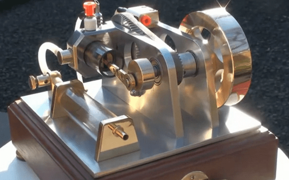
We know a lot about toggling bits in a register, but only a bit about how engines work. This one inspires us to throw ourselves into the field with reckless abandon. [Huib Visser] built this glass cylinder four-stroke engine and he took great care to make it beautiful. We don’t need our projects to be polished and gleaming, but we have to admit that this the opposite of what we see when popping the hood on our 12-year-old rust bucket out front.

You can’t see it in this image, but just on the other side of the fly-wheel is a smaller wheel with a cord wrapped around it that acts as the pull start. This gets the toothed timing belt going along with the cylinder. As part of the demo video we get a good look at how the rotary intake and exhaust valves work. [Huib] also took the time to demonstrate how the rare earth magnets and hall effect sensor reed switch synchronize the ignition system.

You won’t want to miss the end of the video which show it in action as It burns Coleman fuel (white gas) and is lubricated with WD-40. This is jaw dropping and it works like a charm, but still not that far removed from the concepts seen in [Lou’s] hardware store engine project.

UPDATE: Here’s write up this engine (translated) [Thanks ChalkBored]

Continue reading “Four-stroke Engine With Glass Cylinder Is A 2400 RPM Piece Of Art”

Fail Of The Week: Inaugural Edition

We’re sure you’ve all been waiting on the edge of your seats to see whose project makes it as the first Hackaday Fail of the Week. Wait no longer, it’s [Mobile Will] with his woeful tale about monitoring AC current usage.

He had been working on a microcontroller actuated mains outlet project and wanted an accurate way to measure the AC current being used by the device connected to it. The ADE7753 energy metering IC was perfect for this so he designed the board above and ordered it up from OSH Park. After populating the components he hooked it up to his Arduino for a test run, and poof! Magic blue smoke arose from the board. As you’ve probably guessed — this also fried the Arduino, actually melting the plastic housing of the jumper wire that carried the rampant current. Thanks to the designers of the USB portion of his motherboard he didn’t lose the computer to as the current protection kicked in, requiring a reboot to reset it.

We can’t wait to hear the conversation in the comments. But as this is our first FotW post we’d like to remind you: [Mobile Will] already knows he screwed up, so no ripping on his skills or other non-productive dibble. Let’s keep this conversation productive, like what caused this? He still isn’t completely sure and that would be useful information for designing future iterations. Update: here’s the schematic and board artwork.

We’ve got a bit more to share in this post so keep reading after the break.

Continue reading “Fail Of The Week: Inaugural Edition”

Building A Barn Door Tracker For Astronomical Photography

That’s a pretty amazing image to catch peering out from your back balcony. The rig used to record such a gem is seen on the right. It’s called a Barn Door tracker and was built by [DCH972]. Details for this build are scattered all over the place, there’s a video (also found below), another album of some of the best images, and plenty of background info in the Reddit thread.

This design is also know as a Haig or Scotch mount. While we’re dropping links all over the place check out the Wikipedia page on the topic. The point of the system is to move the camera in such a way so that the stars appear to hold in the same place even though the earth is moving. There’s an ATmega32u4 breakout board riding on top of the breadboard. It’s doing some pretty heavy math in order to calculate the stepper motor timing. That’s because the mount is like a photo album, hinged at one side and opened on the other by a ball screw. This linear actuation needs to be meshed with the change in angle of the mounting platform, and finally it needs to sync with the movement of the earth. But once a series of images is captured correctly they can be processed into the composite photograph shown above.

If missed that SDR galactic rotation detector from last May you should find it equally compelling.

Continue reading “Building A Barn Door Tracker For Astronomical Photography”

How To Use The Kenetis KL25Z Freedom Board As An HID Mouse

[Eric] is interested in turning this Freedom development board into an air mouse by using the onboard accelerometer. But he had to work through the particulars of the USB HID mouse class before he could get that done.

This Freescale FRDM-KL25Z is one of the awesome ARM boards we looked at a year ago. Can you believe you can get this thing for like thirteen bucks? We suppose the gotcha is that the CodeWarrior IDE meant for use with them is not entirely free. But there is a free trial, and [Eric] shows how much easier it is to tailor the USB stack for your needs with it.

Don’t worry though. If you’re like us and use Open Source For The Win he’s got you covered as well. When you’re done reading his HID mouse writeup head on over to his six-part tutorial for building a free toolchain for the Kenetis boards.

Soundball Bumps To Your Tunes

soundball-blinks-to-the-music

Meet soundball, a hobby electronics project when replaces a disco ball with one made of LEDs (translated) going every which way. This image shows the device before being injected into an enclosure. The final offering is a white project box with a hole in the top through which the diffuser covered blinky ball is supported.

The main board hosts a collection of the usual suspects: an ATmega328, an MSGEQ7 equalizer, a couple of TLC5940 LED drivers, and a footprint for a Bluetooth Shield. The equalizer chip provides [Cornelius] the audio analysis used to generate light patterns that go along with the music.  But he can still control the lights manually with a button on the case or by connecting to it via Bluetooth.

Swap out the LED drivers for some solid state relays and you can blink your Christmas lights to the music.

Continue reading “Soundball Bumps To Your Tunes”

Taming STM32 Discovery Boards For Regular Use

taming-discovery-boards

We think [Karl Lunt] has a point when he says that the STM32 Discovery Boards are cool and inexpensive, yet not hobby friendly. But it’s nothing that a little big of creativity can’t solve. Above are pictured three of the hacks he used to tame the Discovery boards.

The first is the addition of a microSD card adapter. He soldered wirewrap wire to each of the contacts on the adapter. He recommends a low iron setting to make sure you don’t melt the plastic adapter housing. He then used double stick foam tape to adhere it to the bottom of the dev board. The other ends of the wire are wrapped around the appropriate pins on the dual-row pin header. Similarly, the UART3 connections are broken out from the pin headers to that white quick connect socket. This lets him access serial data without having to solve the USB issues that were vexing him.

Finally, he made his own daughter board to break out the dual row headers into screw terminals. We’ve been hit with problems interfacing hardware with the board’s native connections — jumpering to IDE cables just never worked reliably. This breakout board not only makes it simple, but organizes the pins into groups based on their alternate functions.

Do you remember seeing the hacksaw version of this Discovery board which gives you two dev boards for the price of one?

Retrotechtacular: Singing Bird Automata

retrotechtacular-birdsong-automata

Our cats were both sleeping near the computer and these videos were driving them nuts. To our ears these birdsongs sound pretty good. They didn’t trick the cats into stalking mode, but they did spark an audible complaint. So the predators aren’t drooling but the mechanical engineers reading this should be. These automata combine the precision of a mechanical clock with a bellows and specialized whistle to recreate birdsong.

You’ve got to hear it for yourself to appreciate the variety produced by the mechanisms. The first video shows off the device seen on the left. This particular model is from the 1890’s and the demo gives a good look at the arms that open and block a passageway to alter the sound. After seeing that link — which was sent in by [Stefan] — we started searching around for more info on the devices. The one pictured to the right turned up. It’s from YouTube user [Singing Bird Boxes] who has many videos showcasing these types of devices. We picked this one because he tried to explain how each part of the mechanism works. These are still being made today, but there’s something magical about seeing one built during the steam age.

We’d like to make Retrotechtacular a weekly feature every Tuesday. Help us out by sending in links to projects that highlight old technology, instructional videos of yore, tours of museums or similar relics.

Continue reading “Retrotechtacular: Singing Bird Automata”