Huge Water And Light VU Meter Plus More

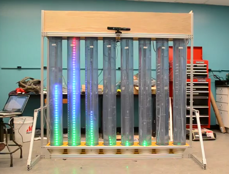
This is the senior design project for a group at the University of Vermont. It’s a wet, bubbly, blinky, interactive thing. Each column is a clear tube filled with water, with a string of fully addressable RGB LEDs suspended in the center. In idle mode, the lights scroll through a series of interesting patterns while the water is filled with bubbles to add some depth to the presentation. There is also a VU meter function, as seen here and during the Portal theme song that ends the video demo after the break.

A Teensy++ board is used to address the display. It’s set up to receive serial commands from a Processing script which is responsible for generating the animations. At the top of the frame you can see there’s a Kinect sensor. By standing in the standard post (we think it should be called the Kinect mug shot) the installation will automatically switch over to body control. We could see this thing making its way into a long airplane terminal hallway, following the travelers along their trek from one terminal to the next.

Continue reading “Huge Water And Light VU Meter Plus More”

Automatic Airplane Tracking; What Radar-systems Engineers Do For Kicks

[G. Eric Rogers] is a radar-systems engineer who just happens to live within sight of the aircraft approach path for the local airport. We wonder if that was one of the criteria when looking for a home? Naturally, he wanted his own home-based system for tracking the airplanes. He ended up repurposing a motorized telescope for this purpose.

The system does not actually use Radar for tracking. Instead, the camera strapped to the telescope is feeding a video experimenter shield. A tracking algorithm analyzes the video and extrapolates vector data. From there, the base unit can be controlled by the Arduino via an RS232 interface.

There are some bugs in the system right now. The Arduino has something of an ADHD problem, losing interesting and going to sleep in the middle of the tracking process. [Eric’s] workaround uses the RS232 board to periodically reset the Arduino, but he hopes to squash this bug soon.

Reaching Out To A Touch Screen With A Microcontroller

We love capacitive touch screens. They’re much more robust than resistive touch screens and if the UI is programmed well they produce a great user experience. But getting your electronics project to interact with one is a bit tough. [RobB] has been experimenting in that area, and managed to build a simple touchscreen actuator for microcontroller use.

In the video after the break you can see his proof of concept. He’s using an Arduino to enter the number 2 on an Android  iOS calculator app once every second. It doesn’t take much to pull off this trick, [RopB] just taped a piece of tin foil to the screen and connected it to the Arduino with a jumper wire. The pin is left floating until a screen tap is needed, at which point it is pulled to ground.

A custom app operating at slow speeds could use this as an input technique. Two pieces of foil (one acting as clock, the other data) would provide a rudimentary serial transfer system.

Continue reading “Reaching Out To A Touch Screen With A Microcontroller”

Creating A Multimedia Elevator Ride

[Ben Peoples] works in theatrical electronics. Sounds like fun, and here’s an example of the kind of stuff he does. We’re not sure what event this installation was used for, but if the elevator ride needed something flashy just think of what the party room must have looked like. These HDTV screens on the ceiling of the elevator play different clips when the elevator is moving up or down. The challenge for [Ben] was to find a way to make it work without tapping into the elevator electronics or requiring any button presses.

The first attempt at sensing the elevator’s travel was done with an accelerometer. The problem with this approach is that an accelerometer only senses change in acceleration and this method proved to be fairly error prone. [Ben] switched over to a reflective sensor which performed quite well. Since most of these sensors will only work within about an eighth of an inch he ended up building his own with a LDR and a couple of amber LEDs.

[via Reddit]

Retrotechtacular: The Blit Has Given Me Access To The Power Of Multiprogramming!

We normally try to be descriptive with our titles. But when that statement pops out of the narration with notable excitement it made us chuckle. This installment of Retrotechtacular is a promotional video for the Blit. It’s a graphics-based hardware terminal for Unix systems. It’s biggest boast is the ability to run (and display on screen) several different programs at once — an activity called multiprogramming. But there is also the “digitizing mouse”. On board is a 68000 microcprocessor 256k of RAM (they call it a quarter meg), and connects via RS232. The screen is 800 by 1024; that’s right, it’s a portrait orientation.

Notable in this episode are some classic eyeglass frames, and rad synthesizer sounds for scene transitions. Whatever happened to videography technique that uses a dimwitted companion to ask that all-knowing narrator stupid questions?

Continue reading “Retrotechtacular: The Blit Has Given Me Access To The Power Of Multiprogramming!”

Arduino PIC Programmer Writes To 18F Family

[Kirill] wrote in to share his Arduino-based PIC programmer. It is capable of writing to the 18F family of chips, including 18F2XXX and 18F4XXX. We think that’s pretty exciting because this line of chips has USB functionality and there are bootloaders out there that let you program them via USB. So if you wanted to build your own PIC dev-board (like this one) you can use your Arduino to flash the bootloader.

This post comes hot on the heels of the Arduino being used as a PIC 16F programmer. That hack has a rudimentary programming GUI, something that [Kirill] admits his lacks but has no plans to implement himself. Perhaps someone will do a little porting work to merge the projects, adding to the range of chips supported by this programming technique.

Watch A Shop Tour Through The Screen Of An Oscilloscope

[Alan] posted a video tour of his electronics shop, but you’ll be viewing it through the green screen of an oscilloscope. The image above is a video camera filming a scope screen which displays the image of…. an oscilloscope (insert your own Yo Dawg meme here). But first he shares the technique he uses to display composite video on an oscilloscope screen.

The first three minutes of the video after the break are devoted to the video display hack. He starts with a glimpse of the breadboard circuit which takes the composite video signal and provides the necessary X, Y, and Z input signals to the scope to perform like this. He then walks through each portion of the schematic, which is based on an LM1881 video sync separator chip. The horizontal and vertical sync signals are separated by this chip, then filtered to produce ramp voltages for each to drive X and Y. The Z-axis is fed through a simple inverter circuit; Bob’s your uncle and your oscilloscope is now a TV monitor.

Of course this is not the first time this has been done. But we loved [Alan’s] presentation, and thought the shop tour was a fun way to finish off the video.

Continue reading “Watch A Shop Tour Through The Screen Of An Oscilloscope”