3D printed moon lamp

3D Printed Lithographic Moon Lamp

After years of being a software developer, [Chris] was excited to get back into embedded development and we’re glad he did. His 3D printed lithographic moon lamp combines a number of hacker and maker skills, and is sure to impress.

3D-printed lithographic moons have gotten pretty popular these days, so he was able to find a suitable model on Thingiverse to start with. Gotta love open-source. Of course, he needed to make a few modifications to fit his end design. Namely, he put a hole at the bottom of the moon, so he could slide the LED and heatsink inside. The 3 watt LED is pretty beefy, so he definitely needed a heat sink to make sure everything stayed cool.

Otherwise, the circuit itself is pretty straightforward. He has an ESP32 to drive the RGB LED through a transistor, and fitted the components onto a custom-designed circuit board to ensure everything stayed neat and organized. You don’t want a ton of loose wires and breadboards cluttering this build. Since he used an ESP32, he was able to create a simple web interface to control the color of the LEDs. Gotta make it connected somehow, right?

What’s great is in addition to the project write-up, [Chris] includes video tutorials, walking the readers through each individual step of the build. By doing so he really makes it easy for readers to follow along and reuse his work. If you’re still looking for ideas, one of these could make a really good Christmas present.

Continue reading “3D Printed Lithographic Moon Lamp”

Assistive Tech And Video Games

Assistive technologies have a pretty big presence here on Hackaday, and this hack is nothing short of interesting. [kerchoo_22] is working on a hands-free video game controller as a final project for her engineering class and we think it’s worth sharing.

The basic premise of the circuit is pretty simple. She DIY’d a few contact switches using conductive plates made of cardboard, duct tape, and aluminum foil. The output of the switch is read by analog input pins on an Arduino Leonardo. When the switches are off, the analog input pins are pulled HIGH using 1 MegaOhm resistors. But when the user hits their head on one of the four conductive pads, the switch is engaged, and the analog input pins are shorted to ground.

The Arduino Leonardo, having a native USB port, is able to directly emulate a keyboard. Each conductive pad is mapped to a different key press corresponding to different functions within the game. Left, right, shoot, etc. And there you have it, gameplay without using hands or a controller!

Now, it seems as though [kerchoo_22] put an appropriate amount of cushion on the head pads, so there probably isn’t much danger of a concussion. Either way, you can never be too careful.

Flux capacitor PCB

Back To The Future We Go With This Flux Capacitor PCB Badge

[Arnov] is a huge fan of the Back to the Future franchise, so he wanted some memorabilia from the movie to decorate his work area. Official memorabilia from successful movie franchises can be pretty expensive, so [Arnov] opted to make something himself instead, creating his own flux capacitor PCB badge.Doc Flux Capacitor Schematic from Back to the Future

Fortunately, [Arnov’s] design isn’t as complicated as Doc’s was from the movie (pictured on the right), so it should be a lot easier to replicate. We have a simple LED circuit driven by an 8205S MOSFET and controlled by an ATtiny microcontroller. There’s a small diode for auto-switching between USB and battery power as well as a few current limiting resistors for the LEDs. Fortunately, [Arnov’s] project only requires 0.017 W to power, so no plutonium nuclear reactor is necessary and you can easily power it with a standard coin cell battery or with a USB. That’s quite a relief.

As with many of [Arnov’s] projects, the beauty in its design lies in the detail he places on the PCB layout. In this case, the layout is a bit easier than some of his other work needing only to arrange the blinking LEDs in a “Y” shape to mirror the flux capacitor seen in the movies. He also adds a bit of detail to the silkscreen to help complete the aesthetic.

We think this is worth adding to your PCB badge collection.

Continue reading “Back To The Future We Go With This Flux Capacitor PCB Badge”

Respiratory rate measuring device attached to volunteer's abdomen along with automated antidote injection system

Researchers Use Wearable To Detect And Reverse Opioid Overdoses In Real-Time

Opioid overdose-related deaths have unfortunately been increasing over the last few decades, with the COVID-19 pandemic exacerbating this public health crisis even further. As a result, many scientists, healthcare professionals, and government officials have been working tirelessly to end this deadly epidemic. Researchers at the University of Washington are one such group and have recently unveiled a wearable to both detect opioid overdose and deliver an antidote, in real-time, restoring normal bodily function.

As the researchers describe in their paper, opioid overdose causes respiratory rate depression which will lead to hypoxia (insufficient oxygen in the blood) and ultimately death. Fortunately, opioid overdose can be readily reversed using naloxone, a compound that binds to receptors in the brain, outcompeting the opiates themselves, and restoring normal breathing. Unfortunately, if someone is overdosing, they are unable to self-administer the antidote and with many opioid overdoses occurring when the victim is alone (51.8%), it is necessary to develop an automated system to deliver the antidote when an overdose is detected.

The researchers begin by describing their process for measuring respiration, of which there are several options. You could use photoplethysmography in much of the same way we measure heart rate. Or you could measure the changing impedance of the chest cavity during breathing or even use an intraoral sensor that measures airflow in the mouth. Instead, the researchers opt to measure respiration by attaching accelerometers to the patient’s abdomen and measuring the movement of the abdominal cavity during breathing. They admit their technique becomes problematic when the patient is not stationary, but argue that in the case of a drug overdose, the patient is likely to be immobilized and the device would be able to measure respiration with ease. They tested their device across dozens of healthy, human volunteers, and even some opiate users themselves, and showed their technique had good agreement with a reference respiratory belt placed around the volunteers’ chests.

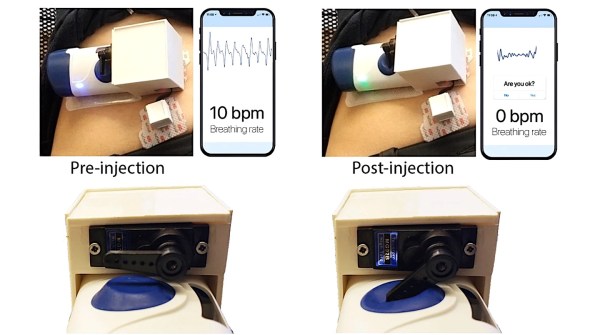
The cool part about this paper is that they demonstrated a “closed-loop” feedback system in which their device measured respiration, detected cessation in breathing (indicating an overdose), and delivered the antidote. To deliver naloxone, they leveraged an existing, commercially-available drug delivery system that requires a user to manually activate the device by pressing a button. They hacked the device a bit such that the trigger could be actuated using a servo motor properly positioned to depress the button when an opioid overdose is detected. They simulated an overdose by asking the healthy, human volunteers to hold their breath for a period greater than 15 seconds. They were able to successfully deliver the antidote to 100% of their volunteer group, indicating the device could potentially work in real-world settings.

Now, the form factor of the device undoubtedly needs to improve in order to deploy this device into the field, but we imagine those are improvements are underway and patients have shown willingness to wear such devices already. Also, there’s still a bit of a question of whether or not accelerometer-based breathing detection is optimal since some drug overdoses cause seizures. Nevertheless, this is an important step in combating the alarming rise in opioid overdose-related deaths and we hope to see many more advances in patient monitoring technologies in this field.

Google Sheet showing wins and losses of sports team. Data automated by IFTTT, Alexa, and Particle

An Overly Complicated Method Of Tracking Your Favorite Sports Team

Much of the world appears to revolve around sports, and sports tracking is a pretty big business. So how do people keep up with their favorite team? Well, [Jackson] and [Mourad] decided to devise a custom IoT solution.

Their system is a bit convoluted, so bear with us. First, they tell Alexa whether or not the team won or lost that week. Alexa then sends that information to IFTTT where two different Particle Argon boards are constantly polling the results to decide how to respond next. One Particle responds by lighting up an LED, green for a win and red for a loss. Another Particle board displays the results on an LCD screen. But this is where things get tricky. One of the more confusing aspects of their design is one of the Particle boards then signals back to IFTTT, telling it to tally the number of wins and losses. This seems a bit roundabout since the system started with IFTTT in the first place. Regardless, they seemed to be happy with the result and I’m sure they learned something in the process.

This project might not fulfill any functional need given that Alexa knows everything about all our lives already and you could just ask her how your favorite team is doing whenever you want to. But hey, we’re all about learning by doing here at Hackaday and we’re all guilty of building useless projects here and there just because we can. In any case, their project could serve as a good intro to integrating your Particle with IFTTT or Alexa since there appears to be quite a bit of probably unnecessary handshaking going on here.

Continue reading “An Overly Complicated Method Of Tracking Your Favorite Sports Team”

iPhone pictured with a lock

Make Your Own BLE-Enabled IOS App From Scratch

Even those readers who are most skeptical of Apple products will like this Bluetooth Low Energy (BLE)-enabled iOS app tutorial from [Akio].

With everything being “connected” these days smartphone applications are of course a ubiquitous part of our existence. We’ve seen plenty of examples connecting your Bluetooth-enabled projects to an Android device, but comparatively fewer tutorials for connecting to iOS devices. This mostly has to do with Android’s much larger market share and also Android’s more open-source friendly business model. Nevertheless, if you do much IoT development either as a hobby or professionally, then you probably find yourself interacting with Apple devices more than you like to admit.

[Akio’s] app is essentially updating a chart, in real-time, with data read from an Adafruit nRF52832 Feather board. He then walks you through all the basics of creating a user interface (UI) using Apple’s Storyboard interface, a simple drag-and-drop scheme similar to something you’ve probably used in many other contexts. [Akio] shows readers how to add buttons for allowing users to interact with the app, labels for displaying data to the user, as well as walks you through Apple’s odd methodology of connecting UI elements to code using IBAction and IBOutlets. The highlight of his tutorial is showing readers how to add charts to their iOS apps which seems to take a few more steps than you might imagine.

[Akio] does a really good job detailing all the relevant functions so that readers will hopefully understand what each piece of the code is doing. And we really enjoyed him adding individual video tutorials for some of the trickier programming steps. He also readily admits that some folks may opt to develop their UI exclusively in code as opposed to the Storyboard but he argues that the Storyboard is still important for beginners and is really handy when the UI is fairly simple.

Of course, in true open-source fashion, [Akio] provides all his code on his GitHub repository so you can clone the repo and run the code yourself as well as credit some of the resources he used while making his app. Two things we really love to see. Hopefully, [Akio’s] tutorial will make connecting to iOS devices seem much less onerous than it once was.

Christmas tree PCB with Blinky Circuit

Is It Finally Time For Christmas Decorations?

[Arnov] is trying to get into the holiday spirit and is doing so the way he knows how. He was thinking of some cool decorations for his Christmas tree and decided the best decorations are the ones you make yourself, so he made his own blinky Christmas tree ornament.

The famed “blinky circuit” is certainly one that we are no strangers to here at Hackaday. Some of our readers will be very pleased to see that he did in fact use a 555 timer and not an Arduino. The 555 timer is wired to drive the clock pin of the CD4017 decade counter and the outputs of the decade counter are wired to the LEDs. The LEDs are lit up sequentially upon each low to high transition of the clock pulse though you may try getting creative with your LED wiring scheme to achieve different blinking effects.

What readers might really take away from this build is [Arnov] detailing how to import images into his CAD tool of choice, OrCAD in his case. We know that can be a bit tricky sometimes. Finally, we love that this project doubles as PCB art and a soldering challenge. It would definitely make for a good demo project at your next beginner soldering workshop.

Cool project [Arnov!]

Continue reading “Is It Finally Time For Christmas Decorations?”