Customized IPad LCD Screen Clips Onto Macbook As A Slick Second Screen

Macbook with iPad second screen

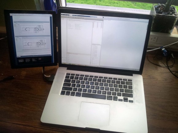
Last year, [Ben] found a good deal on iPad 3 LCD screens. He couldn’t resist buying a couple to play around with. It didn’t take him long to figure out that it’s actually quite simple to use these LCD screens with any computer. This is because the LCD panels have built-in Apple Display port interfaces. This means that you can add your own Display Port connector to the end of the LCD’s ribbon connector and just plug it into a computer. You’ll also need to hook up a back light driver, which [Ben] was able to find pre-made for around $35.

The hack doesn’t stop there, though. [Ben] wanted to have a nice, finished product. He laser cut an acrylic bezel for the LCD screen that was a perfect fit. He then milled out a space for the LCD to fit into. The acrylic was thick enough to accommodate the screen and all of the cables. To cover up the back, [Ben] chose to use the side panel of a PowerMac G5 computer case. He chose this mainly for aesthetics. He just couldn’t resist the nice brushed aluminum look with the giant Apple logo. It would be a perfect match to his Macbook.

Once the LCD panel was looking nice, [Ben] still needed a way to securely fasten it in the right place. He knew he’d want it next to his Macbook, so why not attach it directly to the Macbook? [Ben] got to work with his 3D printer and printed up some small plastic clips. The clips are glued to the iPad screen’s acrylic bezel and can be easily clipped on and off of the Macbook screen in seconds. This way his laptop is still portable, but he has the extra screen real estate when he needs it. [Ben] also printed up a plastic clip that turns the iPad’s USB power connector and the Display Port connector into one single connector. While this is obviously not required, it does effectively turn two separate plugs into one and makes the whole project that much more slick.

Track Your Dog With This DIY GPS Harness

GPS-dog-harness

Have you ever wondered how far your dog actually runs when you take it to the park? You could be a standard consumer and purchase a GPS tracking collar for $100 or more, or you could follow [Becky Stern’s] lead and build your own simple but effective GPS tracking harness.

[Becky] used two FLORA modules for this project; The FLORA main board, and the FLORA GPS module. The FLORA main board is essentially a small, sewable Arduino board. The GPS module obviously provides the tracking capabilities, but also has built-in data logging functionality. This means that [Becky] didn’t need to add complexity with any special logging circuit. The GPS coordinates are logged in a raw format, but they can easily be pasted into Google Maps for viewing as demonstrated by [Becky] in the video after the break. The system uses the built-in LED on the FLORA main board to notify the user when the GPS has received a lock and that the program is running.

The whole system runs off of three AAA batteries which, according to [Becky], can provide several hours of tracking. She also installed a small coin cell battery for the GPS module. This provides reserve power for the GPS module so it can remember its previous location. This is not necessary, but it provides a benefit in that the GPS module can remember it’s most recent location and therefore discover its location much faster. Continue reading “Track Your Dog With This DIY GPS Harness”

How To Upgrade Jasper’s Voice Recognition With AT&T’s Speech-to-Text API

Jarvis upgrade

Jasper is an open-source platform for developing always-on voice-controlled applications — you talk and your electronics listen! It’s designed to run on a Raspberry Pi. [Zach] has been playing around with it and wasn’t satisfied with Jasper’s built-in speech-to-text recognition system. He decided to take the advice of the Jasper development team and modify the system to use AT&T’s speech-to-text engine.

The built-in system works, but it has limitations. Mainly, you have to specify exactly which keywords you want Jasper to look out for. This can be problematic if you aren’t sure what the user is going to say. It can also cause problems when there are many possibilities of what the user might say. For example if the user is going to say a number between one and one hundred, you don’t want to have to type out all one hundred numbers into the voice recognition system in order to make it work.

The Jasper FAQ does recommend using the AT&T’s speech-to-text engine in this situation but this has its own downsides. You are limited to only one request per second and it’s also slower to recognize the speech. [Zach] was just fine with these restrictions but he couldn’t find much information online about how to modify Jasper to make the AT&T engine work. Now that he’s gotten it functional, he shared his work to make it easier for others.

The modification first requires that you have at AT&T developer account. Once that’s setup, you need to make some changes to Jasper’s mic.py module. That’s the only part of Jasper’s core that must be changed, and it’s only a few lines of code. Outside of that, there are a couple of other Python scripts that need to be added. We won’t go into the finer details here since [Zach] goes into great detail on his own page, including the complete scripts. If you are interested in using the AT&T module with your Jasper installation, be sure to check out [Zach’s] work. He will likely save you a lot of time.


DIY Newton’s Cradle Uses Parts Designed On A Smart Phone

Injection Molded Parts

As far as physics demonstrations go, the Newton’s Cradle is probably one of the most recognizable. Named after Sir Isaac Newton, the Newton’s Cradle demonstrates the law of conservation of momentum using swinging ball bearings.

[Scorchworks] decided he wanted to build his own Newton’s Cradle. The frame appears to be cut from MDF or particle board and then screwed together. That material is really easy to obtain and also to work with using inexpensive tools. The tricky part was the ball bearings. Most of the time when you see a Newton’s Cradle, the ball bearings have a small hole drilled in the top with an eye hook attached. The string is then attached to the eye hook.

[Scorchworks] decided to do something different. His plan was to make custom injection molded plastic rings that would fit perfectly around the ball bearings. The most interesting thing is that he designed the injection molding plates entirely on his smart phone while at his child’s baseball practice. To do this, [Scorchworks] used his own Android app, ScorchCAD. ScorchCAD is a free clone of OpenSCAD that is designed to run on Android devices. Most of the functionality of OpenSCAD has been implemented in ScorchCAD, though not all functions work yet. You can find a list of all the supported functions on the project’s website or in the Google Play store.

Once the plates were designed within ScorchCAD, [Scorchworks] exported the STL file and then used Meshcam to generate the gcode for his CNC milling machine. Once he had the plates machined, he just placed the ball bearing into the mold and injected the molten plastic around it. The plastic formed a perfectly shaped ring around the bearing with small loops for the string. [Scorchworks] repeated the process several times to get all of the ball bearings finished.

Finally, the bearings were strung up using some fishing line. A Newton’s Cradle is very sensitive to the positioning of the ball bearings. To account for this, [Scorchworks] tied each end of the fishing line to two different screws on top of the cradle. This way, each screw can be tightened or loosened to adjust the position of each ball bearing.

Fight The Google Glass Cyborgs With Glasshole.sh

Glasshole script

We live in a connected world where social media is ubiquitous and many people feel compelled to share every waking moment with anyone who will listen. In this type of world, wearable computers like Google Glass allow us to share experiences like never before. A Glass user can take photos, record video and audio, or potentially even stream video live on the Internet with the greatest of ease. That might be great for the Glass user, but what about the rest of us? As wearable computing becomes more and more mainstream, people are naturally going to become divided on the issue of privacy. Is it a good thing to have “cyborgs” with wearable computers and cameras constantly at the ready, or is it a privacy nightmare? The cyborg war is coming, and [Julian] has already chosen his side.

It would seem that [Julian] lands on the side of the privacy advocates, based on his “glasshole” script. Glasshole is a relatively simple bash script that relies on some other common network security tools to take care of the heavy lifting. The basic premise relies on the fact that every manufacturer of network interface devices is assigned their own MAC prefix. This is a piece of the MAC address that is unique to that manufacturer.

[Julian’s] script uses a utility called arp-scan to obtain a list of all MAC addresses on a given wireless network. It then loops through each address and compares it to the known Google Glass MAC prefix. If it finds a match, it will make an audible beeping noise to alert the script user. The script then launches aireplay-ng in de-authentication mode. This will send spoofed disassociate packets to the client (in this case the Google Glass device), hopefully forcing them to disconnect from the access point. The script runs continuously, ensuring that once the device reconnects to the network it will get booted off once again. The script is designed to be run on a small Linux computer such as a Raspberry Pi or a BeagleBone black. This way, the user can carry it around with them as a sort of portable defense mechanism.

How do you fit into the cyborg war? Will you stand proudly with your computer on your face for all to see? If so, what kind of countermeasures would you deploy to prevent this type of attack from working on you? If not, what other types of interesting attacks can you think of to keep the cyborgs at bay?

[Thanks Syed]

NES RetroPi

Original NES Guts Upgraded With RetroPie

If you have an old broken NES lying around and have no idea what to do with it, you may want to check out [snoius’s] latest project. He replaced the guts of his old NES with a Raspberry Pi. [snoius] started out by removing most of the electronics from his original NES to make room for the Pi. He left the original control panel board so he would be able to use the original power button and power LED. The NES power switch is an on/off toggle switch. [snoius] decided to just route the 5V USB power input directly through this switch. The result is a hard power switch for the tiny computer. The original power LED is wired up to the Pi’s 3.3V GPIO header through a 330 ohm resistor. Now when the Pi has power, the LED lights up.

The next step was controllers. It looks like [snoius] is using some USB SNES controller clones. He wanted to use the original NES controller ports but obviously the NES did not utilize USB. [snoius] used a saw to cut the backs off of the controller ports, leaving a flat surface. He then used a utility knife to carve out a hole in the shape of a female USB port. He mounted some ports in place and then wired the inside up to some short USB cables with male ends. These were plugged into a USB hub that is hidden inside of the NES case.

The Pi is also hooked up to a short HDMI cable and a short power cable. The loose ends of the cables are mounted to a small block of wood. Notches are cut out of the wood to better fit the cable ends. The rear of the NES has two holes cut out where the original connectors used to be in order to accommodate the new connectors.

With all of the hardware taken care of, [snoius] still needed a way to actually play his games. That’s where RetroPie saved the day. RetroPie is a Linux distribution for the Raspberry Pi that is specifically created to make it easy to play old video games. It includes emulators for many old systems including NES, SNES, SEGA Genesis, Gameboy, etc. [snoius] installed RetroPie onto an 8GB SD card and copied over all of the ROMs he could find. The end result is what appears to be an original NES at a glance, but is in fact multiple retro gaming systems in one. It also contains hundreds of video games in on board memory instead of requiring a large library of physical cartridges.

[via reddit]

HAL Is Duct Tape For Home Automation

HAL Home Automation

When it comes to home automation, there are a lot of different products out there that all do different things. Many of them are made by different companies, and they don’t often play very well together. This frustration ultimately led [Daniel] to develop his own Python based middleware solution to get these various components to work as a single cohesive system. What exactly did [Daniel] want to control?

First up was the door lock. [Daniel] lives in an apartment building, so there are actually two locks. First, a visitor must be allowed into the building by pressing a button on the intercom system in the apartment. Second, the apartment door has its own dead bolt lock that needs to be opened and closed. [Daniel] was able to control the building’s front door using just a transistor hooked up to an Arduino to simulate the press of the physical button. The original button remains in tact so [Daniel] can still easily “buzz” in a visitor.

The apartment’s dead bolt was a bit trickier. There are off-the-shelf solutions to control a dead bolt, but they are often expensive. [Daniel] built his own solution using a simple servo motor bolted to the door. The servo is controlled by the Arduino which is in turn controlled via two broken intercom buttons that already existed within the apartment. The buttons were originally used to either speak to or listen to a visitor before buzzing them into the building. They had never worked for [Daniel] so he re-purposed them for his own project. The whole DIY door locker is enclosed in a custom-made laser cut wooden box.

Click past the break for the rest of [Daniel’s] story.

Continue reading “HAL Is Duct Tape For Home Automation”