A blue PCB remote control

The Remoteduino Nano Is A Tiny IR Remote That’s Truly Universal

Universal remotes are extremely convenient if they work correctly. But setting them up can be quite a hassle: often, you need to browse through long lists of TV models, key in the codes on the remote with just a blinking LED as confirmation, and then pray that the manufacturer included the correct codes for all your equipment. IR isn’t a very complicated technology, however, so it’s perfectly possible to roll your own universal remote, as [sjm4306] shows in his latest project, the Remoteduino Nano. It’s a fully programmable IR remote that gives you maximum flexibility when emulating the codes for those obscure A/V systems scattered around your home.

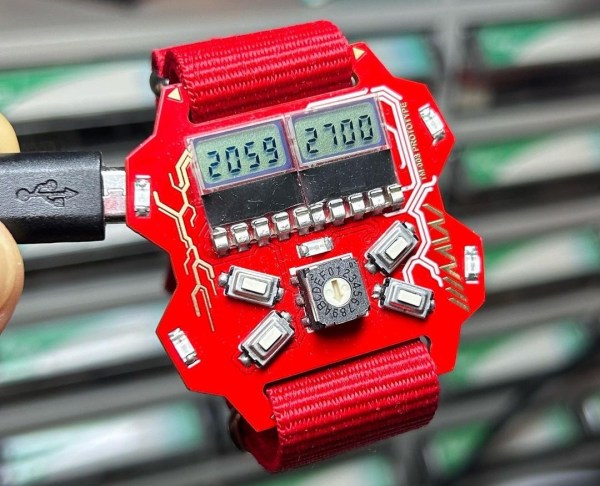
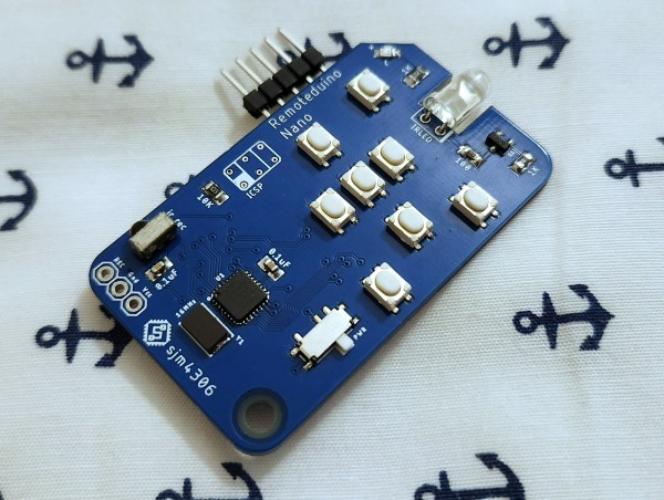
The remote runs on an ATmega328p in a tiny QFN package, which drives a standard 5 mm IR LED through a transistor. Eight buttons are available to the user, which can be freely mapped to any desired code. A five-pin header is included to program the ATmega through its serial port. However, this was mainly done to help debug – a user who only needs to program the device once would typically use a pogo-pin-based adapter instead.

Currently, codes can only be programmed through the serial port, but there’s also an IR receiver present that can be used to copy codes from an existing remote. [sjm4306] hasn’t implemented this feature in software yet, but will probably do so in a future update of the project’s Arduino sketch. If you’re impatient, you can also have a go at it yourself since all code and the board’s Gerber files are freely available for download.

Its tiny size makes the Remoteduino Nano a convenient tool to keep in your drawer if you like to tinker with A/V systems and keep losing those remotes. The Nano is actually an improved version of the original Remoteduino project that [sjm4306] developed a couple of years ago. The problem of a truly universal remote is one that dates back several decades, however.

Continue reading “The Remoteduino Nano Is A Tiny IR Remote That’s Truly Universal”

A wristwatch based on a red PCB with seven-segment LCD screens

The Time Machine Mk. 8 Is A Sleek Smartwatch With Retro Styling

The primary purpose of a wristwatch is to tell the time, which pretty much any watch does perfectly fine. It’s in the aesthetics, as well as features other than time-telling, where a watchmaker can really make their product stand out from the rest. Watchmaker and electronic artist [Eric Min] focused on those two areas when he designed the Time Machine Mk.8, which combines exquisite design with simple, offline smartwatch functionality.

The heart of the watch is a Microchip ATSAMD21G18 low-power 32-bit microcontroller. [Eric] chose it for its high performance, ease of use and large number of integrated peripherals, a real-time clock being one of them. With the basic clock function thus taken care of, he then decided to add several useful sensors: a battery fuel gauge to keep an eye on the 40 mAh rechargeable lithium cell, a three-axis accelerometer to enable motion sensing and an environmental sensor to track temperature, humidity and pressure.

A faux 1980s magazine ad for a red PCB wristwatchThe various functions are operated using four pushbuttons along with a 16-step rotary encoder set in the middle. The overall design of the watch is inspired by Formula 1 steering wheels, as well as various sports cars and media franchises like Neon Genesis Evangelion and Akira. [Eric] considered a few different options for the display but eventually settled on two four-digit seven-segment LCDs, which fit nicely into the retro-futuristic aesthetic of the Mk.8. It’s so retro, in fact, that it almost makes [Eric]’s faux 1980s magazine ad look genuine.

All components neatly fit together on a dual-layer PCB, which is a true work of art in itself. From the lightning bolt on the front to the hidden Frank Sinatra lyrics, it definitely stands out from the crowd of ordinary LCD wristwatches. It’s also quite a step up from [Eric]’s previous watch design, the Time Machine Mk.IV.

Over the years we’ve seen several other examples of how a bare PCB, or even a stack of them, can become a beautiful wristwatch.

A Nintendo 64 controller with a USB adapter

Play N64 Games The Right Way With This Classic Controller Adapter

Game consoles typically support a limited number of input devices, meaning that console games are often completely optimized for the default controller supplied with that platform. Nintendo’s tendency to completely reinvent their controllers pretty much every generation can therefore become a little irritating, especially when they also enable their newer consoles to play games from their back catalog. So when [Robson Couto] found that using the Switch’s Joy-Cons was a bit awkward for playing emulated Nintendo 64 games, he decided to figure out how to connect real N64 controllers to a Nintendo Switch.

While you can buy modern N64-style controllers for the Switch, even straight from Nintendo themselves, [Robson] thought it would be way more interesting to reuse an old controller and implement the translation step from scratch. In the video (embedded below) he takes a deep dive into all the timing details of the N64 controller protocol, which is basically a 1-wire setup, and explains how to use an STM32F411 BlackPill board to read out the controller’s buttons and joystick.

Next, he explores how to map the resulting data to the USB HID protocol used by the Switch. Most of the buttons have a clear one-on-one mapping, but since the “minus”, “capture” and “home” buttons are missing on the N64 controller, he chose to map these to button combinations unlikely to be used during regular gameplay. [Robson] also ran into the common issue of the analog joystick having a poorly-defined maximum range, for which he added a rudimentary auto-calibration feature.

Finally, he designed and 3D-printed a neat enclosure for his system with an N64 controller port on one side and a USB port on the other. By 3D-printing the whole thing he also avoided having to either source the non-standard connector or permanently modify his hardware. The end result of [Robson]’s project is an unobtrusive gadget that connects classic controllers to modern hardware – but of course, the reverse process is very much possible, too. If you want, you can even play N64 games with a mouse and keyboard.

Continue reading “Play N64 Games The Right Way With This Classic Controller Adapter”

A set of solderless breadboards with op amps and their functions annotated

Op-Amp Challenge: Virtual Ball-in-a-Box Responds To Your Motions

With the incredible variety of projects submitted to our Op-Amp Contest, you’d almost forget that operational amplifiers were originally invented to perform mathematical operations, specifically inside analog computers. One popular “Hello World” kind of program for these computers is the “ball-in-a-box”, in which the computer simulates what happens when you drop a bouncy ball into a rigid box. [wlf647] has recreated this program using a handful of op amps and a classic display, and added a twist by making the system sensitive to gravity.

All the physics simulation work is performed by a set of TL072 JFET input op amps. Four are configured as integrators that simulate the motion of the ball in the X and Y directions, while four others serve as comparators that detect the ball’s collisions with the edges of the box and give it a push in the opposite direction. Three more op amps are connected to form a quadrature oscillator, which makes a set of sine and cosine waves that draw a circle representing the ball.

A miniature CRT viewfinder showing a small circleThe simulator’s output signals are connected to a tiny viewfinder CRT as well as a speaker that makes a sound whenever the ball hits one of the screen’s edges. This makes for a great ball-in-box display already, but what really makes this build special is the addition of an analog MEMS accelerometer that modifies the gravity vector in the simulation.

If you tilt or shake the sensor, the virtual box experiences a similar motion, which gives the simulation a beautiful live connection to the real world. You can see the result in a demo video [wlf647] recently posted.

The whole setup is currently sitting on a solderless breadboard, but [wlf647] is planning to integrate everything onto a PCB small enough to mount on the viewfinder, turning it into a self-contained motion simulator. Analog computers are perfect for this kind of work, and while they may seem old-fashioned, new ones are still being developed.

Detail of a circuit sculpture in the shape of a lighthouse

Op Amp Contest: This Lighthouse Sculpture Flickers In The Rhythm Of Chaos

Op amps are typically used to build signal processing circuits like amplifiers, integrators and oscillators. Their functionality can be described by mathematical formulas that have a single, well-defined solution. However, not every circuit is so well-behaved, as Leon Chua famously showed in the early 1980s: if you make a circuit with three reactive elements and a non-linear component, the resulting oscillation will be chaotic. Every cycle of the output will be slightly different from its predecessors, and the circuit might flip back and forth between different frequencies.

A circuit sculpture in the shape of a lighthouseA light modulated with a chaotic signal will appear to flicker like a candleflame, which is the effect [MaBe42] was looking for when he built a lighthouse-shaped circuit sculpture. Its five differently-colored LEDs are driven by a circuit known as Sprott’s chaotic jerk circuit. A “jerk”, in this context, is the third-order derivative of a variable with respect to time – accordingly, the circuit uses three RC integrators to implement its differential equation, along with a diode to provide nonlinearity.

The lighthouse has three chaotic oscillators, one in each of its legs. Their outputs are used to drive simple pulse-width modulators that power the LEDs in the top of the tower. [MaBe42] used the classic LM358 op amp for most of the circuits, along with 1N4148 diodes where possible and 1N4004s where needed – not for their higher power rating, but for their stronger leads. As is common in circuit sculptures, the electronic components are also part of the tower’s structure, and it needs to be quite sturdy to support its 46 cm height.

[MaBe42] used 3D printed jigs to help in assembling the various segments, testing each circuit before integrating it into the overall structure. The end result is a beautiful ornament for any electronics lab: a wireframe structure with free-hanging electronic components and randomly flickering lights on top. Want to learn more about circuit sculpture? Check out this great talk from Remoticon 2020.

Continue reading “Op Amp Contest: This Lighthouse Sculpture Flickers In The Rhythm Of Chaos”

Front and back views of a square, purple PCB with op amps and BNC outputs

Op Amp Contest: Generate Spirograph Shapes Using Only Op Amps And Math

If you’re a child of the ’80s or ’90s, chances are you’ve spent hours tracing out intricate patterns using the pens and gears of a Spirograph kit. Simple as those parts may be, they’re actually a very clever technique for plotting mathematical functions called hypotrochoids and epitrochoids. [Craig] has spent some time analyzing these functions, and realized you can also implement them with analog circuits. He used this knowledge to design a device called Op Art which generates Spirograph shapes on your oscilloscope using just a handful of op amps.

A spirograph shape shown on an oscilloscope screenTo draw either a hypotrochoid or an epitrochoid, you need to generate sine and cosine waves of various frequencies, and then add them with a certain scaling factor. Generating sines and cosines is not so hard to do with op amps, but making an adjustable oscillator that reliably churns out matching sine and cosine waves over a large frequency range turned out to be tricky. After a bit of experimentation, [Craig] discovered that a phase-shift oscillator was the right topology, not only for its adjustability but also because it generates sine, cosine and inverted sine terms that all come in handy when drawing various Spirograph shapes. Continue reading “Op Amp Contest: Generate Spirograph Shapes Using Only Op Amps And Math”

A man playing an automated recorder

Musical Robot Lets You Play The Recorder Hands-Free

Although many people might remember the recorder as just a simple instrument from their introductory music classes, it can nevertheless produce rich and varied melodies in the hands of a virtuoso like Frans Brüggen. [Luis Marx] also took music lessons as a child, but never progressed much beyond an elementary level. Instead, he preferred to spend his time honing his engineering skills, which eventually enabled him to get back into music.

Initially, he wanted to build a piano-playing exoskeleton, to marionette his fingers up and down the ivories, but had to bail on that one because of the insane complexity. So instead, he built himself a robot that helps him play the recorder. (Video, in German, embedded below, fast-forwarded to the recorder part.)

A set of solenoids and an Arduino on a 3D-printed frameA recorder has eight finger holes, which can be covered or uncovered in various combinations to produce tones. [Luis] therefore used eight solenoids, mounted on a 3D-printed frame, to actuate the finger holes. The basic idea worked, but getting the solenoids to fully cover the holes each time turned out to be a challenge: even a slight misalignment would cause air to leak past the plug and produce a horrible off-key sound.

After a lot of trial and error, [Luis] found foam earplugs to be a pretty good material for emulating human fingertips. He also discovered that relying on the solenoids’ spring tension to keep the holes closed was not reliable; a better solution was to flip the solenoids around and use the much larger force from their powered stroke to create an air-tight seal.

The solenoids are driven by an Arduino Nano through a set of MOSFET modules, powered by a lithium battery. [Luis] wrote some Arduino sketches with famous melodies like Beethoven’s Für Elise, which sound quite decent on the robo-recorder: perhaps not on Frans Brüggen’s level, but pretty impressive for a self-declared “music noob” like [Luis].

Many robotic musicians play instruments like pianos or xylophones. Instruments from the flute family are harder to automate, but it has been done before. We’ve even seen a MIDI-powered harmonica.

Continue reading “Musical Robot Lets You Play The Recorder Hands-Free”