A DR-DOS console showing the IDLE command

Missing DR-DOS Power Management Source Code Found In Patent

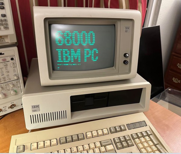
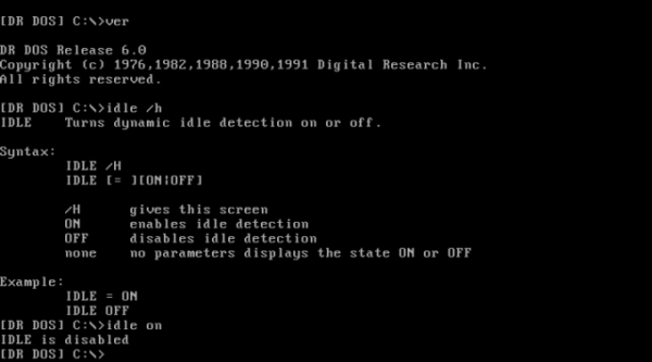
Modern processors come with all kinds of power management features, which you don’t typically notice as a user until you start a heavy program and hear the CPU fan spin up. Back in the early 1990s however, power management was largely unheard of, meaning that a CPU with nothing to do would run through an idle loop that dissipated about as much power as a real computing task. [Michal Necasek] noticed this while experimenting with DR-DOS 6.0 in a virtual machine – his laptop fan would start running on full blast whenever he opened the VM. His search for a solution to this annoyance led him down a fascinating journey into the intricacies of DOS power management.

As it turned out, DR-DOS 6.0 does have functionality built in for putting the CPU in power saving mode when it’s idle. This feature is not complete, however: Digital Research required each computer manufacturer to develop an IDLE driver customized to their specific hardware platform in order to enable power management. Sadly, no manufacturer ever bothered to do so, leaving [Michal] with no option other than writing a driver himself. While there was some documentation available, it didn’t include any example code or sufficient detail to write a driver from scratch.

A snippet of x86 assembly code found in a patent
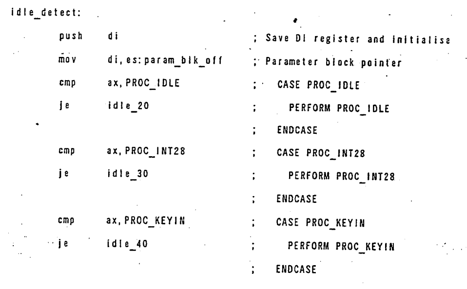
What it did include was a reference to U.S. Patent No. 5,355,501. Normally this sort of information is of interest only to those planning to sell a competing system, but this specific patent happens to include dozens of pages of well-documented but poorly-scanned x86 assembly code, including source code for a basic IDLE86.SYS driver. As [Michal] wasn’t looking forward to chasing bugs caused by OCR errors, he simply copied the source code by hand, then ran it through an assembler. The end result was a working IDLE driver, which is now available for download from his website.

[Michal]’s blog post also includes lots of details on early power saving implementations, including all the DOS interrupt calls involved in the process. Patents might seem boring in contrast, but they sometimes contain surprising amounts of usable information. You might find enough details to reverse-engineer a wireless protocol, or even to help track down an obscure instrument’s original designer.

A clock made with LED displays and reflective film

Clever Optics Make Clock’s Digits Float In Space

If you’ve never heard of Aerial Imaging by Retro-Reflection, or AIRR for short, you’re probably not the only one. It’s a technique developed by researchers at Utsunomiya University that uses beam splitters and retroreflective foil to create the illusion of an image floating freely in the air. Hackaday alum [Moritz v. Sivers] has been experimenting with the technique to make — what else — a clock, appropriately called the Floating Display Clock.

The most commonly available retroreflective films are typically used for things like street signs and high-visibility clothing, but also work perfectly fine for homebrew AIRR setups. [Moritz] tried several types and found that one called Oralite Superlens 3000 resulted in the best image quality. He combined it with a sheet of teleprompter glass and mounted both in their appropriate orientation in a black 3D printed enclosure.

An inside view of a clock based on the AIRR projection techniqueThe projected image is generated by a set of 8×8 RGB LED displays, which are driven by a PCA9685 sixteen-channel servo driver board. A Wemos D1 Mini fetches the time from an NTP server and operates the display system, which includes not only the LED panels but also a set of servos that tilt each digit when it changes, giving the clock an added 3D effect that matches nicely with the odd illusion of digits floating in space.

We can imagine it’s pretty hard to capture the end result on video, and the demonstration embedded below probably doesn’t do it justice. But thanks to [Moritz]’s clear step-by-step instructions on his Instructables page, it shouldn’t be too hard to replicate his project and see for yourself what it looks like in real life.

Although this isn’t a hologram, it does look similar to the many display types that are commonly called “holographic”. If you want to make actual holograms, that’s entirely possible, too.

Continue reading “Clever Optics Make Clock’s Digits Float In Space”

A miniature 486 desktop PC running Lemmings

Tiny 3D Printed Gaming PC Contains Real Retro Hardware

Emulators are easy and convenient, but for some retrocomputing enthusiasts nothing comes close to running classic software on actual era-appropriate hardware. This can become a problem, though, for those into vintage PC gaming: old PCs and their monitors are notoriously large and heavy, meaning that even a modest collection will quickly fill up a decent family home. There is a solution however, as [The Eric Experiment] demonstrates in his latest video. He designed and built a 3D-printed mini PC that runs on an actual 486 processor.

An ordinary desktop motherboard would have required a rather large case to begin with, so [Eric] started his project by buying an old industrial PC board. Such a device has the processor and all main motherboard components sitting on an ISA card, which then connects to other ISA cards through a backplane. This way, a complete system with expansion cards can be made way more compact than even the sleekest desktop PCs of the time. An SD-card-to-IDE converter makes for an extremely slim hard drive replacement, while a Gotek floppy emulator allows the system to boot as if there’s actually a floppy drive present.

A small 486 tower case being assembled
Even the side panels slide in exactly like they do on real PC cases.

All of this is pretty neat to begin with, but by far the most impressive parts of the Tiny 486 project are the enclosures that [Eric] designed for the PC and its accompanying monitor. Both were modelled off real-world examples and are accurate down to the smallest details: the tilting stand that clips onto the base of the monitor for instance, or the moving latch on the faux 5.25″ floppy drive. That latch operates a cleverly hidden door that reveals the USB connector for the floppy emulator. The compulsory seven-segment LED display on the mini tower’s front panel now finally serves a useful purpose – indicating which floppy image is currently active.

Sporting an Intel 486-DX4 100 MHz processor, 32 MB of RAM, a Tseng ET4000 video card and an ESS Audiodrive for sound, the tiny 486 can run DOS or Windows 95, although performance in the latter is a bit limited due to the lack of a local-bus video card. It’s perfectly fine for most DOS games though, and a lot more practical than a full-sized desktop PC.

There are several ways to make a tiny game PC, like using PC/104 standard boards or repurposing old network equipment. The crucial part needed to turn it into a gaming machine is a proper sound card, which you can even build from scratch if needed. Thanks for the tip, [Nathan]!

Continue reading “Tiny 3D Printed Gaming PC Contains Real Retro Hardware”

An IBM PC showing "68000 IBM PC" on its monitor

IBM PC Runs BASIC With Motorola 68000 CPU Upgrade

Although ARM CPUs have been making headway in several areas of computing over the last decade or so, the vast majority of desktop, laptop and server CPUs are still based on the x86 architecture. How that came to be is no secret, of course: IBM chose the Intel 8088 to power its model 5150 PC back in the early 1980s, and since it became the dominant PC platform, everyone else followed suit. But what if IBM’s purchasing department had got a good deal at Motorola instead? [Ted Fried] has been experimenting with that scenario, by equipping an IBM PC with a 68000 CPU.

To be fair, he didn’t use an actual Motorola chip; instead, he emulated a 68k core on a Teensy 4.1 and implemented the 8088’s bus interface on its pins. The emulated core does exactly the same thing an actual CPU would do, while the rest of the computer works the same way it always did – data is stored in the motherboard’s DRAM chips, keystrokes are processed by the standard 8255 chip and progam output is displayed on the monitor through the MDA video card. Continue reading “IBM PC Runs BASIC With Motorola 68000 CPU Upgrade”

An IN-12B Nixie tube on a compact driver PCB

Modern Components Enable Cheap And Compact Nixie Driver Circuit

Nixie tubes can add some retro flair to any project, but they can also complicate your electronics quite a bit: after all, you need to generate a voltage high enough to ignite the tube and then switch that between ten separate display segments. Traditionalists may want to stick with chunky mains transformers and those unobtainium 74141 segment drivers, but modern components allow you to make things much more compact, not to mention way cheaper. [CNLohr] took this to an extreme, and used clever design tricks and his sharp online shopping skills to make an exceptionally compact Nixie driver circuit that costs less than $2.50.

That price doesn’t include the tubes themselves, but [CNLohr] nevertheless bought the cheapest Nixies he could find: a pair of IN-12B tubes that set him back just $20. He decided to generate the necessary 180 volts through a forward converter built around a $0.30 transformer and a three-cent MOSFET, controlled by software running on a CH32V003. This is one of those ultra-cheap microcontrollers that manage to squeeze a 48 MHz RISC-V core plus a bunch of peripherals into a tiny QFN package costing just 12 cents.

The existing toolchain to program these micros left a lot to be desired, so [CNLohr] wrote his own, called
ch32v003fun. He used this to implement all the control loops for the forward converter as well as PWM control of the display segments – a feature that adds a beautifully smooth turn-on and turn-off effect to the Nixie tubes. There’s still plenty of CPU capacity left to implement other features, although [CNLohr] isn’t sure what to put there yet. Turning the tubes into a clock would be an obvious choice, but the basic system is flexible enough to implement almost anything requiring a numeric display.

The compactness of this circuit is impressive, especially if you compare it to earlier solutions. There’s plenty of fun to be had with cheap-yet-powerful micros like the ch32v003, provided you can find them.

Continue reading “Modern Components Enable Cheap And Compact Nixie Driver Circuit”

An electronic neuron implemented on a purple neuron-shaped PCB

Hackaday Prize 2023: Explore The Basics Of Neuroscience With This Electronic Neuron

Brains are the most complex systems in the universe, but their basic building blocks are surprisingly simple — the complexity arises from billions of neurons, axons and synapses working together. Simulating an entire brain therefore requires vast computing resources, but if it’s just a few cells you’re interested in, you don’t need much: a handful of op-amps and transistors will do the job, as [Sebastian Billaudelle] has demonstrated. He has designed an electronic neuron called Lu.i that does everything a real neuron does, in a convenient package suitable for educational use.

[Sebastian]’s neuron implements what’s known as the leaky integrate-and-fire model, first proposed by [Louis Lapicque] as a simple model for a neuron’s behavior. Basically, the neuron acts as an integrator that stores all incoming charge in a capacitor and generates a spiky output signal once its voltage reaches a certain threshold level. The capacitor is slowly discharged however, which means the neuron will only “fire” when it gets a strong enough input signal.

Two neuron-shaped PCBs exchanging signalsA couple of MCP6004 op-amps implement this model, with an LM339 comparator acting as the threshold detector. The neuron’s inputs are generated by electronic synapses made from logic-level MOSFETS. These circuits route signals between different neurons and can be manually set to either source or sink current, thereby increasing or decreasing the neuron’s voltage level.

All of this is built onto a neat purple PCB in the shape of a nerve cell, with external connections on the tips of its dendrites. The neuron’s internal state is made visible by an LED bar graph, giving the user an immediate feel for what’s going on inside the network. Multiple neurons can be connected together to form reasonably complex networks that can implement things like oscillators or logic functions, examples of which are shown on the project’s GitHub page.

The Lu.i project is a great way to teach the basics of neuroscience, turning dry differential equations into a neat display of signals racing around a network. Neurons are fascinating things that we’re learning more about every day, enabling things like brain-computer interfaces and neuromorphic computing.

A modern DRAM board for the Heathkit H8 computer

Versatile DRAM Board Adds Memory To Any Heathkit H8 Variant

Ask anyone to name a first-generation home computer from the 1970s, and they’ll probably mention the likes of the Altair 8800 and IMSAI 8080. But those iconic machines weren’t the only options available to hobbyists back in the day: Heathkit, famous for its extensive range of electronic devices sold in kit form, jumped on the microcomputer bandwagon with their H8. Though it always remained a bit of an obscure machine, several dedicated enthusiasts kept making H8-compatible hardware and software long after the computer itself went out of production. That tradition continues in 2023, with [Scott M. Baker] producing a brand-new DRAM board that’s compatible with any version of the H8.

Although the Heathkit H8 was designed around the Intel 8080 processor, it could also be equipped with a Z80. [Scott] had built an 8085 based CPU board as well, meaning that any other hardware he developed for the H8 had to support these three processors. For something as timing-critical as a memory board, this turned out to be way harder than he’d expected.

First off, he had already made things difficult for himself by choosing DRAM rather than the simpler SRAM. Whereas SRAM chips can be more or less directly hooked up to the CPU’s address and data buses, a DRAM setup needs refresh circuitry to ensure the data doesn’t leak out of the chips’ internal capacitors. [Scott] decided to use the classic D8203 DRAM controller to do that for him — a solution that was pretty common back in the day.

Getting the timing right for all signals between the CPU and the DRAM controller was not at all trivial, however. The main problem was with two signals, called /SACK and /XACK, which were used to pause memory access during refresh cycles. Depending on which CPU was on the other side, these signals apparently had to be combined with other signals, stored in a flip-flop or delayed by a cycle or two in order to align with the processor’s internal logic. None of this seemed to work reliably, so [Scott] looked elsewhere for inspiration.

A vintage DRAM board for the Heathkit H8 computer
Luckily, traces are easy to follow on a two-layer board.

He found this on eBay, where a few vintage H8-compatible DRAM boards were for sale. Although [Scott] didn’t manage to win the auction, the eventual buyer was kind enough to snap some high-resolution pictures of the board which enabled him to reverse-engineer the circuit. The board used the similar D8202 DRAM controller and came with logic that generated the proper signals to interface with the 8080 and 8085 CPUs. For the Z80, [Scott] dived into the documentation for Heathkit’s Z80 option and found a schematic with a few logic gates that would satisfy the Zilog chip as well.

[Scott] combined both of these solutions on a beautiful 1980s-style printed circuit board, with a bunch of 7400 series logic gates and even two GAL22V10 programmable logic devices. With full documentation and Gerber files available on the project’s GitHub page, Heathkit H8 owners can now get their own brand-new memory board — in kit form, as a Heathkit should be.

There are several enthusiasts keeping the various Heathkit computer models up and running, and even producing completely new ones. The Heath Company also still exists, selling electronic kits to this day.

Thanks for the tip, [Adrian]!