How To Get Good With Wood

It’s perhaps unsurprising that we don’t see much in the way of woodworking here at Hackaday; after all, this is a plastics and metal community if there ever was one. But that doesn’t mean you’ll never come across a situation where a dead tree needs to be cut or shaped to your will, so we appreciate [Eric Strebel] demonstrating some tips and best practices for working with this exceptionally versatile building material.

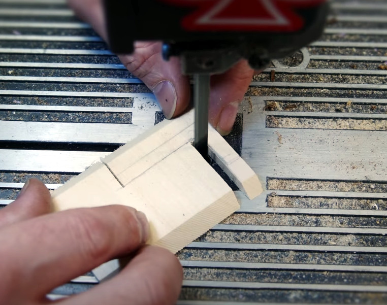
The first video assumes you’re a lumber neophyte, and goes over topics such as the different species of wood you’re likely to find at the hobby shop, proper sanding technique, and the differences between cutting with and against the grain. Some of the different cutting tools you can use are also covered, ranging from the humble hobby knife to the band saw. As always, [Eric] sprinkles the video with tips and tricks gained from his considerable professional experience, such as using some glue and a bit of sawdust to fill in any gaps left behind by an uneven joint.

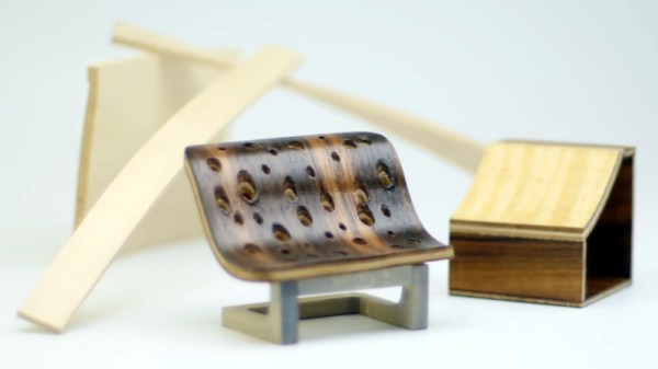
In the second video, things start getting more advanced. [Eric] demonstrates how you can create custom laminates, and how wood can be permanently bent into arbitrary shapes with sufficient steam and clamping pressure. By combining these new techniques with the basic concepts covered in the first video, surprisingly complex shapes can be formed with minimal effort.

[Eric] previously put together a similar series of videos on working with acrylic, a material that’s arguably far more familiar to the Hackaday readership. But whatever material you use, the takeaway message from this series is clear: get the right tools, learn the techniques, and professional results are well within your reach.

Continue reading “How To Get Good With Wood”

Wearable Scope Lets Your Fingers Do The Probing

For frantic hacking sessions where seconds count, this forearm mounted oscilloscope with fingertip probes built by [aniketdhole] might be just what you need. Well, maybe. It’s not immediately clear why you might want to wear an oscilloscope on your arm, and sticking your fingers inside of powered up electronic devices sounds specifically like something your mother probably told you not to do, but here it is anyway.

The scope consists of an nRF5340 evaluation board in a 3D printed mount, with an SPI-connected Adafruit 2.8″ TFT display on top. With a pair of wires run from the board’s ADC and ground pins, [aniketdhole] just needed a bit of code to glue it all together and show some basic signal visualizations on the display. It’s been tested against PWM signals generated by an Arduino and some potentiometer controlled voltages, but anything much wilder than that is probably a bit too much to ask for from this rig in its current configuration.

In the future, [aniketdhole] wants to add some step-down circuity so you can probe higher voltages than the nRF5340 can handle normally, as well as a shunt to allow current measurement. Once the hardware is in place, the next order of business will be an improved touch-capable user interface that lets the user adjust settings and switch between functions.

Even if you’re not sold on the idea of an arm-mounted oscilloscope, this is still an interesting platform for general wearable experimentation. Throw enough sensors into it, and we’re sure there’s more than a few hackers who wouldn’t mind strapping one of these on.

Pi Pico Emulates ROM For Speedy Retro Hacking

If you’ve ever worked on a system that loads its software from a ROM or EPROM, you know how much of a hassle it can be to make frequent changes to the code. Pulling the chip, flashing it, and sticking it back into the socket each time you change a line isn’t anyone’s idea of a good time. Which is why [Nick Bild] has come up with the PicoROM, a way to emulate a ROM chip using the Raspberry Pi Pico.

With the Pi Pico standing in for the original ROM, updating firmware takes a fraction of the time and doesn’t require you to actually disconnect any of the hardware. [Nick] had done something similar with FPGAs in the past, but the far cheaper and easier to work with Pi Pico makes this version particularly appealing. The secret to getting it to work is the overclocking potential of the Pico, which he says has been pushed to 400 MHz for this particular application.

PicoROM on a breadboard.

The downside is that you can’t access the Pico’s onboard flash when the chip is running that fast. To get around that limitation, all of the code is loaded into the microcontroller’s RAM. With a healthy 264 KB of memory this isn’t really a problem when emulating 32 KB chips, but [Nick] says his method would quickly fall apart for larger ROMs.

Beyond the Pi Pico itself, [Nick] is using a trio of 74LVC245AN 8-bit logic level shifters so the chip can talk to the 5 V logic of his homebrew 6502 computer. With everything wired up on a simple breadboard, PicoROM has no trouble serving up the operating system as it hums along at 2 MHz.

Of course, a modern high-performance microcontroller isn’t strictly necessary. In the past we’ve covered devices that could emulate an EPROM using 1990s era silicon.

A Microcontroller Friendly AR Headset On The Cheap

Generating the real-time images required for augmented reality (AR) goggles usually requires a fair amount of processing power, to the point that DIY efforts based around the Raspberry Pi often have trouble keeping up. But what if your AR aspirations don’t require fancy high-resolution graphics? If text and the occasional icon is enough to get the job done, then these lo-fi AR goggles from [bobricius] might be the ideal solution.

As with previous homebrew AR rigs we’ve seen, this one starts with an affordable headset designed to project the display of a smartphone onto a pair of curved optical combiners. But instead of tucking a phone into the headset, [bobricius] is using a custom PCB that holds a pair of ST7789 1.3 inch 240 x 240 IPS displays. Connected over SPI and supported by just about any microcontroller you’d care to use, tossing some textual data over your field of vision can be accomplished in just a few lines of code.

[bobricius] has actually put together a couple different versions of the PCB for this project. One uses his custom ATSAMD21E18-based “ArmaBrain” module that packs the MCU and an array of common components onto a 28 mm square board that can be easily dropped into other projects. If you’d rather roll your own solution, the second version of the board that simply holds the two displays in the appropriate position and routes the SPI lines to a convenient header should do nicely.

We’ve seen augmented reality displays using microcontrollers like the ESP32 before, but those were essentially just remote displays for a more powerful system. We like this simplified approach, as there are plenty of applications where just getting a few lines of text or some low-resolution images would be more than sufficient for the task at hand. Plus, the commercially-made headset this project is based on certainly looks better than some of the other donor goggles we’ve contemplated modifying in the past.

Continue reading “A Microcontroller Friendly AR Headset On The Cheap”

Upgrade Board Adds GPIO Pins To Your Replica PDP-11

Like many Hackaday readers, [Steven Stallion] has had his eyes on the replica PDP-11 created by [Oscar Vermeulen] for some time now, and this summer he finally got the opportunity to build one himself. But while most owners might be content to just watch the Raspberry Pi based faux-retro computer blink away on a shelf, he wanted to explore putting the machine to more practical use. The end result is the PiDP-11 I/O Expander,  an add-on that lets the modern minicomputer interact with the world around it.

Developed after some discussion with [Oscar] himself, the Microchip MCP23016 based expander board fits neatly onto the PiDP-11 PCB, and [Steven] has made sure his installation guide meshes well with the replica’s documentation. The Pi’s I2C bus is actually broken out on the original PCB, so you just need to solder a header on and run some jumpers to where the expander is mounted. You’ll need to pull 5 V as well, and the installation guide has a few tips on convenient connection points.

The installed PiDP-11 I/O Expander

Each expander board gives you 16 GPIO pins which can be accessed over I2C, including support for interrupts which has been connected to GPIO 19 on the Raspberry Pi. [Steven] notes that you should be able to stack multiples of his expander up should you need even more free pins, though some fiddling with pull-up resistors and I2C addresses will likely be necessary.

The PCBs for the expander have been released under the two clause BSD license, so you’re free to spin up your own copies however you see fit. But if you’d like to save some time, [Steven] is offering assembled boards on Tindie.

Since [Oscar] first teased it at the 2015 Hackaday Supercon, we’ve been enamored with his fantastic PDP-11 replica. We’re always glad to see when somebody has picked up one of these wonderful kits, and doubly so when they’ve figured out a way to expand it in unexpected ways.

See The Unseen With This Magnetic Field Visualizer

The average Hackaday reader likely knows, at least in the academic sense, what a magnetic field looks like. But as the gelatinous orbs in our skull can perceive only a tiny fraction of the EM spectrum, we have to take those textbook diagrams at face value. That is, unless you’ve got one of these nifty magnetic field visualizers developed by [Dr.Stone].

Using an XMC1100 microcontroller development board and a TLV49 3D magnetic sensor, the device is able to track the poles of a magnet in real-time and produce an approximation of what the field lines would look like on its electronic paper display. Relative field strength is indicated by the size of the visualization, which allows the user to easily compare multiple magnets. Incidentally, [Dr.Stone] notes that the current version of the hardware and software can only handle one magnet at a time; visualizing complex magnetic fields and more than two poles would take an array of sensors and likely a more powerful processor.

Do you need to visualize the field lines around a magnet? Perhaps not. But being able to quickly get an idea of how strong a magnet is and identify where its poles are could certainly come in handy. We’d like to see [Dr.Stone] take the project to the next phase and turn this into a handheld device for convenient workbench use. It would be a lot less messy than some of the previous methods we’ve seen for visualizing magnetic fields, though if you’re only worried about field strength, there’s arguably more straightforward ways to display it.

Continue reading “See The Unseen With This Magnetic Field Visualizer”

So How Does A Rocket Fly Sideways, Anyway?

It’s often said that getting into orbit is less about going up, and more about going sideways very fast. So in that sense, the recent launch conducted by aerospace startup Astra could be seen as the vehicle simply getting the order of operations wrong. Instead of going up and then burning towards the horizon, it made an exceptionally unusual sideways flight before finally moving skyward.

As you might expect, the booster didn’t make it to orbit. But not for lack of trying. In fact, that the 11.6 meter (38 feet) vehicle was able to navigate through its unprecedented lateral maneuver and largely correct its flight-path is a testament to the engineering prowess of the team at the Alameda, California based company. It’s worth noting that it was the ground controller’s decision to cut the rocket’s engines once it had flown high and far enough away to not endanger anyone on the ground that ultimately ended the flight; the booster itself was still fighting to reach space until the very last moment.

Astra’s rocket on the launch pad.

There’s a certain irony to the fact that this flight, the third Astra has attempted since their founding in 2016, was the first to be live streamed to YouTube. Had the company not pulled back their usual veil of secrecy, we likely wouldn’t have such glorious high-resolution footage of what will forever be remembered as one of the most bizarre rocket mishaps in history. The surreal image of the rocket smoothly sliding out of frame as if it was trying to avoid the camera’s gaze has already become a meme online, arguably reaching a larger and more diverse audience than would have resulted from a successful launch. As they say, there’s no such thing as bad press.

Naturally, the viral clip has spurred some questions. You don’t have to be a space expert to know that the pointy end of the rocket is usually supposed to go up, but considering how smooth the maneuver looks, some have even wondered if it wasn’t somehow intentional. With so much attention on this unusual event, it seems like the perfect time to take a close look at how Astra’s latest rocket launch went, quite literally, sideways.

Continue reading “So How Does A Rocket Fly Sideways, Anyway?”