When you really start fine-tuning your 3D printer, you might start to notice that even the smallest things can have a noticeable impact on your prints. An open window can cause enough of a draft to make your print peel up from the bed, and the slightly askew diameter of that bargain basement filament can mess up your extrusion rate. It can be a deep rabbit hole to fall down if you’re not careful.
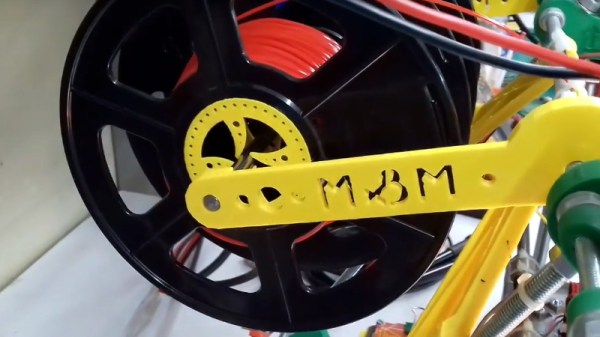
One element that’s often overlooked is the filament spool; if it’s not rotating smoothly, the drag it puts on both the extruder and movement of the print head can cause difficult to diagnose issues. For his custom built printer, [Marius Taciuc] developed a very clever printable gadget that helps the filament roll spin using nothing but the properties of the PLA itself. While the design might need a bit of tweaking to work on your own printer, the files he’s shared should get you most of the way there.
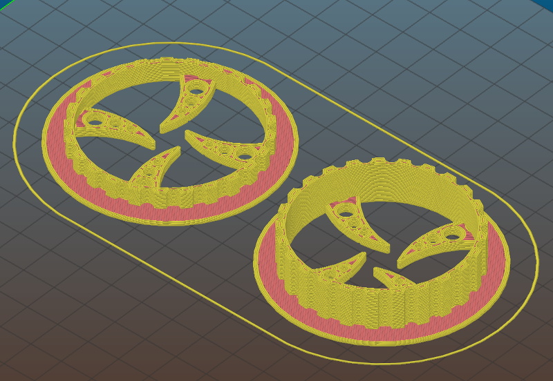 All you need to do is print out the hubs which fit your particular filament spools (naturally, they aren’t all a standard size), and snap them on. The four “claws” of the hub lightly contact a piece of 8 mm rod enough to support the spool while limiting the surface area as much as possible. The natural elasticity of PLA helps dampen the moment that would result if you just hung the hub-less spool on the rod.
The STL files [Marius] has provided for his low-friction hubs should work fine for anyone who’s interested in trying out his design, but you’ll need to come up with your own method of mounting the 8 mm rod in a convenient place. The arms he’s included are specifically designed for his customized Prusa Mendel, which is pretty far removed from contemporary desktop 3D printer design. Something to consider might be a piece of 8 mm rod suspended over the printer, with enough space that you could put a couple spools on for quick access to different colors or materials.
Hackers have been trying to solve the spool friction issue for years, and as you might expect we’ve seen some very clever designs in the past. But we especially like how simple [Marius] has made this design, and the fact that you don’t need to source bearings to build it. If you’re thinking of giving this new design a shot, be sure to leave a comment so we know how it worked out for you.
Continue reading “Printable Filament Spool Hub Skips The Bearings”