Smart Power Strip Revived With Raspberry Pi

We’re all for buying broken stuff from eBay to save yourself a few bucks: buy it cheap, fix it, and reap the rewards of being a step ahead of the average consumer. Searching through the “For parts or not working” categories is nearly the official pastime here at the Hackaday Bunker. But buying an eBay find only to have it give up the ghost in a couple weeks? That hurts.

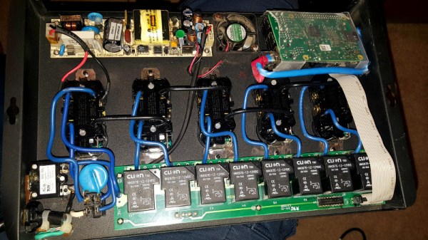
That’s precisely what happened to [idaresiwins] when he bought this beefy looking “Web Power Switch” on the Electronic Bay. After two weeks, the controller board blew and his “smart” power strip became very stupid indeed. But with the addition of a Raspberry Pi, he’s got it back up and running. Not only that, but given the extra horsepower this device now contains, it now doubles as a basic server for the home lab.

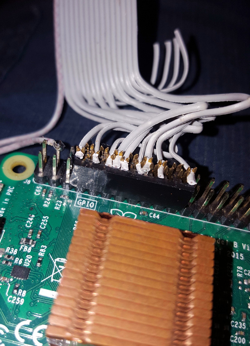
This conversion was helped by the fact that the original controller was on a separate board from the relays, and connected with a small ribbon cable. All [idaresiwins] had to do was figure out which wire in the cable went to each of the eight relays, and fire them off with the Pi’s GPIO pins. In an interesting detail, he opened up one of the ends of the ribbon cable and used it as a punch down block of sorts to easily hook the wires up to the Pi’s pins. We might suggest some hot glue to keep everything from moving around, but otherwise it’s a neat tip.

[idaresiwins] found some information online about making a web-based GPIO interface, which he adapted to control the outlets on the power strip. He then wrapped the Pi up in plastic to keep it from shorting out, and tucked it inside the case. Note that he was able to pull 5 VDC from the relay board and run it to the Pi over the ribbon cable, so he didn’t need to bother with hacking a USB adapter in there.

Controlling AC devices over the Interwebs is an extremely popular project, and we’ve even seen a DIY device that looks quite similar to this product. Most of them are now using the ESP8266, but with the Pi onboard this hack is more like a super-sized version of the PowerPwn.

Dollar Store PCB Holder System

As you get into electronic fabrication and repair, one of the first things you realize is how hard it can be to hold a PCB still while you work on it. Securing them is difficult due to their very nature: they’re often weird shapes, quite fragile, and of course need to be electrically isolated. If you don’t mind spending the money, and have the time to wait on it getting delivered, you can order some nice purpose-built systems for holding PCBs online. But what if you need something fast and cheap?

[Paul Bryson] might have the solution for you. On his blog he’s documented how a trip to the dollar store and some parts from the junk bin allowed him to create a practical system for holding multiple PCBs of various shapes and sizes. The most exotic element of the build here are the hexagonal standoffs; and if you haven’t already salvaged a bunch of those from a curbside computer, he even gives the Mouser link where you can buy them new for a few cents each.

Each individual stanchion of the system is made up of a 3/4″ round magnet with a hex standoff glued to the top. Over the standoff, [Paul] slipped a rubber grommet which gives a nice non-conductive slot to put the edge of the PCB in. Otherwise, a second hex standoff screwed into the first can be used to clamp down on the board. Adjusting the height is as simple as adding a couple more magnets to the stack.

Of course, magnets need something metal to stick on. For that, [Paul] purchased some steel pie pans and matching rack from the dollar store. The round pans are easy to handle and give him plenty of surface area, and the rack makes for an exceptionally convenient storage unit for all the components. The conductivity of the pans might be a concern, but nothing the application of a rubberized spray coating couldn’t fix.

We’ve covered similar systems before, but this one certainly looks to take the top spot in terms of economics. The only thing that would be cheaper would be a few feet of PLA filament and a rubber band.

Solar Pi Cluster Scours Internet For Nudes

There seems to be a universal truth on the Internet: if you open up a service to the world, eventually somebody will come in and try to mess it up. If you have a comment section, trolls will come in and fill it with pedantic complaints (so we’ve heard anyway, naturally we have no experience with such matters). If you have a service where people can upload files, then it’s a guarantee that something unsavory is eventually going to take up residence on your server.

Unfortunately, that’s exactly what [Christian Haschek] found while developing his open source image hosting platform, PictShare. He was alerted to some unsavory pictures on PictShare, and after he dealt with them he realized these could be the proverbial tip of the iceberg. But there were far too many pictures on the system to check manually. He decided to build a system that could search for NSFW images using a trained neural network.

The nude-sniffing cluster is made up of a trio of Raspberry Pi computers, each with its own Movidius neural compute stick to perform the heavy lifting. [Christian] explains how he installed the compute stick SDK and Yahoo’s open source learning module for identifying questionable images, the aptly named open_nsfw. The system can be scaled up by adding more Pis to the system, and since it’s all ARM processors and compute sticks, it’s energy efficient enough the whole system can run off a 10 watt solar panel.

After opening up the system with a public web interface where users can scan their own images, he offered his system’s services to a large image hosting provider to see what it would find. Shockingly, the system was able to find over 3,000 images that contained suspected child pornography. The appropriate authorities were notified, and [Christian] encourages anyone else looking to search their servers for this kind of content to drop him a line. Truly hacking for good.

This isn’t the first time we’ve seen Intel’s Movidius compute stick in the wild., and of course we’ve seen our fair share of Raspberry Pi clusters. From 750 node monsters down to builds which are far more show than go.

Junk Bin Self Balancing Bot With ESP8266

As we all know, sometimes the projects we plan simply never materialize. You have an idea, maybe even buy some of the parts you need, and then…nothing. Maybe you changed your mind, or maybe the idea was never that good to begin with. In any event, time marches on, the parts pile up, and the ideas come and go. Such is the life of the hacker.

[Andrius Mikonis] writes in to tell us how his graveyard of abandoned projects ended up providing exactly what he needed to embark on a project he’s been fascinated with for years: the two-wheel self balancing robot. He started with a motor and wheel set that was originally intended to be part of a rover, added an accelerometer, and tied the whole thing together with an ESP-01 he had lying around. The final result certainly looks the part, and goes to show that projects don’t always need to be 1000 hour labors of love to accomplish their goals.

The construction of this little bot is simple in the extreme. A piece of plywood makes up the primary structure, with the wheels glued to the bottom and the electronics taking up residence in the top. It’s powered by two lithium battery cells that were salvaged out of an old laptop, with a DC-DC buck converter to provide a stable 3.3 VDC for the ESP-01 and MPU6050 accelerometer. To control the motors themselves, [Andrius] is using a cheap L293 controller that he found on eBay.

For interactive control, [Andrius] is making use of the ESP’s Wi-Fi to provide a web-based interface. This lets you control the bot from essentially any device that has a browser, rather than having to use a dedicated hardware transmitter.

Self-balancing robots of various levels of complexity are a relatively common project in the hacker world. There’s just something magical about the way they scoot around, seeming to defy gravity.

ESP8266 Keeps Tabs On The Kid’s Tablets

Assuming you have a child and it’s no longer womb-bound, there’s a fairly high chance they’ve already had some experience with the glowing beauty that is the LCD display; babies of only a few months old are often given a tablet or smartphone to keep them occupied. But as the child gets to the age where they are capable of going outside or doing something more constructive, staring slack-jawed and wide-eyed at their tablet becomes a concern for many parents.

[Richard Garsthagen] is one such parent. He wanted a way to monitor and control how much time his children were using their iPad, so he came up with an automated system based on the ESP8266. Not only does it keep track of how long the tablet is being used, it even includes a reward system which allows the parent to add extra usage time for good behavior.

At the most basic level, the device is a sort of “holster” for the child’s tablet. When the tablet is placed in the slot, it presses a microswitch at the bottom of the cavity which stops the timer. When the switch is open, the LED display on the front of the device counts down, and the ESP8266 pushes notifications about remaining time to the child’s device via IFTTT.

Time can be added to the clock by way of RFID cards. The cards are given out as a reward for good behavior, completion of chores, etc. The child only needs to pass the card in front of the system to redeem its value. Once the card has been “spent”, the parent can reset it with their own special card.

It’s a very slick setup, making perfect use of the ESP8266. Reading the RFID cards, updating the timer, and using IFTTT’s API keeps the little board quite busy; [Richard] says it’s completely maxed out.

You might be wondering what happens when the clock reaches zero. Well, according to the video after the break…nothing. Once the time runs out, a notification simply pops up on the tablet telling them to put it away. Some might see this as a fault, but presumably it’s the part of the system where humans take over the parenting and give the ESP8266 a rest.

This isn’t the first time we’ve seen a microcontroller used to get the little hackers on schedule. At least (so far) none of them have gone full Black Mirror and started tracking when the kiddos are watching it.

Continue reading “ESP8266 Keeps Tabs On The Kid’s Tablets”

Open Source DIY Printers Are Alive And Well: What We Saw At ERRF 18

If you follow the desktop 3D printer market, it probably won’t surprise you to hear that nearly every 3D printer on display at the inaugural East Coast RepRap Festival (ERRF) was made in China. Even Printrbot CEO Brook Drumm had to admit that this was the year his company may finally bite the bullet and begin selling a branded and customized printer built overseas.

When you can get a decent (but let’s be clear, not great) 3D printer for $200 USD, it’s no surprise that American and European manufacturers are having a hard time staying competitive. But not everyone is seduced by low-cost printers. They know they could buy a decent printer for a couple hundred bucks, but for them that’s not the point. Some hackers are just as (if not more) interested in designing and building the machines than they are churning out little plastic boats with the finished product.

Luckily for us, these are also the type of folks who document their builds and make all their collected information and design files available for others under an open source license. Such builders exemplify the true spirit of the RepRap movement, and we’re happy to report that in a sea of imported printers, there were several interesting home built open source printers.

Whether you want to build your own copy of one of these machines, or simply get inspired by some of the ideas their creators had, these machines are physical proof that just because you can order a cheap 3D printer on eBay right now doesn’t mean you have to.

Continue reading “Open Source DIY Printers Are Alive And Well: What We Saw At ERRF 18”

The A To Z Of Building Your Own Keyboard

We’ve featured a number of people who’ve taken the plunge and created their own customized keyboard; at this point it’s safe to say that there’s enough information and source code out there that anyone who’s looking to build their own board won’t have much trouble figuring out how to do so. That being said, it’s nice to have a comprehensive at a process from start to finish. Why sift through forum posts and image galleries looking for crumbs if you don’t have to?

That’s precisely what makes this write-up by [Maarten Tromp] so interesting. He walks the reader through every step of the design and creation of his customized keyboard, from coming up with the rather unique layout to writing the firmware for its AVR microcontroller. It’s a long read, filled with plenty of tips and tricks from a multitude of disciplines.

After looking at other custom boards for inspiration, [Maarten] used OpenSCAD to create a 3D model of his proposed design, and had it printed at Shapeways. His electronics are based around an Atmel ATMega328P using vUSB, and Microchip MCP23017 I/O expanders to connect all the keys. He wrapped it all up by designing a PCB in gEDA PCB and having it sent off for production. As a testament to his attention to detail, everything mated up on the first try.

[Maarten] is happy with the final product, but mentions that in a future revision he would like to add RGB lighting and use a microcontroller that has native USB support. He’d also like to drop the I/O expanders and switch over to Charlieplexing for the key matrix.

From uncommon layouts to diminutive technicolor beauties, it seems there’s no end of custom keyboards in sight. We aren’t complaining.