Multiextrusion 3D Printing And OpenSCAD

In a recent posting called Liar’s 3D Printing, I showed you how you can print with multiple filament colors even if your printer only has one extruder and hot end. It isn’t easy, though, and a lot of models you’ll find on sites like Thingiverse are way too complicated to give good results. An object with 800 layers, each with two colors is going to take a lot of filament changes and only the most patient among us will tolerate that.

What that means is you are likely to want to make your own models. The question is, how? The answer is, of course, lots of different ways. I’m going to cover how I did the two models I showed last time using OpenSCAD (seen below). The software is actually really well suited for this hack, making it easy for me to create a framework of several models to represent the different colors.

About OpenSCAD

I’m not going to say much about OpenSCAD. It is less a CAD package and more a programming language that lets you create shapes. We’ve covered it before although it changes from time to time so you might be better off reading the official manual.

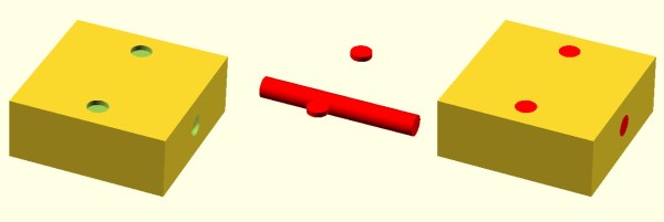
The general idea, though, is you use modules to create primitives. You can rotate them and translate them (that is, move them). You can also join them (union) and take the difference of them (difference). That last is especially important. For example, look at the callsign plate above. Forget the text for now. See the two holes? Here’s the OpenSCAD that creates that shape:

 difference() {
 cube([basew,basel,basez]);
 // cut holes
 translate([4,basel/2,0]) cylinder(r=2,h=basez+2);
 translate([basew-4,basel/2,0]) cylinder(r=2,h= basez+2);
 }

The cube “call” creates the base. The cylinders are the holes and the difference “call” is what makes them holes instead of solid cylinders (the first thing is the solid and everything after is taken away). One key point: instead of numbers, the whole thing uses (mostly) variables. That means if you change the size of something, everything will adjust accordingly if you wrote the script well. Let’s look at applying these techniques for multiple colors.

Continue reading “Multiextrusion 3D Printing And OpenSCAD”

Relay Computing

Recently, [Manuel] did a post on making logic gates out of anything. He mentioned a site about relay logic. While it is true that you can build logic gates using switch logic (that is, two switches in series are an AND gate and two in parallel are an OR gate), it isn’t the only way. If you are wiring a large circuit, there’s some benefit to having regular modules. A lot of computers based on discrete switching elements worked this way: you had a PCB that contained some number of a basic gate (say, a two input NAND gate) and then the logic was all in how you wired them together. And in this context, the SPDT relay was used as a two input multiplexer (or mux).

In case you think the relay should be relegated to the historical curiosity bin, you should know there are still applications where they are the best tool for the job. If you’re not convinced by normal macroscopic relays, there is some work going on to make microscopic relays in ICs. And even if they don’t use relays to do it, some FPGAs use mux-based logic inside.  So it’s worth your time to dig into the past and see how simply switching between two connections can make a computer.

Mux Mania

How do you go from a two input mux to an arbitrary logic gate? Simple, if you paid attention to the banner image. (Or try it interactive). The mux symbols show the inputs to the left, the output to the right and the select input at the bottom. If the select is zero, the “0” input becomes the output. If the select is one, the “1” input routes to the output.

Continue reading “Relay Computing”

Print Flexible PCBs With A 3D Printer

Let’s get it out of the way right up front: you still need to etch the boards. However, [Mikey77] found that flexible plastic (Ninjaflex) will adhere to a bare copper board if the initial layer height is set just right. By printing on a thin piece of copper or conductive fabric, a resist layer forms. After that, it is just simple etching to create a PCB. [Mikey77] used ferric chloride, but other etchants ought to work, as well.

Sound simple, but as usual, the devil is in the details. [Mikey77] found that for some reason white Ninjaflex stuck best. The PCB has to be stuck totally flat to the bed, and he uses spray adhesive to do that. Just printing with flexible filament can be a challenge. You need a totally constrained filament path, for one thing.

Continue reading “Print Flexible PCBs With A 3D Printer”

Programming Thousands Of AVRs

It is funny how almost everything has its own set of problems. Rich people complain about taxes. Famous people complain about their lack of privacy. It probably won’t happen us, but some Kickstarter campaigners find they are too successful and have to scale up production, fast. We’d love to have any of those problems.

[Limpkin] found himself in just that situation. He had to program several thousand Atmel chips. It is true that you can get them programmed by major distributors, but in this case, he wanted unique serial numbers, cryptographic keys, and other per-chip data programmed in. So he decided to build his own mass programming workbench.

Continue reading “Programming Thousands Of AVRs”

Documentation By Markup

Things seem to go in cycles. Writing a document using old-fashioned tools like TROFF or LaTeX is like knowing a secret code. Visual editors quickly took over, although even WordStar had some “dot commands” that you put in as text. Then HTML showed up and we were back to coding formatting as text strings.

Fast forward to the present, and HTML’s ubiquity makes that seem normal. Sure, there are visual editors, but it seems perfectly normal now to write <b> for bold text. However, as HTML grows to handle more tasks it also gets more complex. That’s led to the creation of things like Markdown which is just for simple text formatting. Continue reading “Documentation By Markup”

High-Power LED + 3D Printer = Mega Flashlight

If you remember old computer magazines (or browse them today), you’ll see that back in the late 1970s and early 1980s, you weren’t always sure what you were going to do with a computer. Games were a staple, but they weren’t very exciting. Visionaries talked about storing recipes, writing Christmas letters (to send via snail mail), and keeping home inventories. You probably don’t do any of those things with your computer today, unless you count e-mailing instead of sending Christmas cards. We think sometimes 3D printers fall into that category today. Sure, you want one. But what are you really going to do with it? Print keychains?

That’s why we always like seeing practical designs for 3D printed items. Like this 100W flashlight. The electronics part of the build is simple enough: a 100W LED module, an off-the-shelf driver board, plus an old PC cooler and some batteries. But the 3D printed parts makes it all come together and it looks great!

Continue reading “High-Power LED + 3D Printer = Mega Flashlight”

[Dave’s] Not Just A Member Of The Air Club For Tweezers

We are always surprised how much useful hacking gear is in the typical craft store. You just have to think outside the box. Need a hot air gun? Think embossing tool. A soldering iron? Check the stained glass section. Magnification gear? Sewing department.

We’ve figured out that people who deal with beads use lots of fine tools and have great storage boxes. But [Dave] found out they also use vacuum pickup tweezers. He had been shopping for a set and found that one with all the features he wanted (foot pedal, adjustable air flow, and standard tips) would run about $1000.

By picking up a pump used for bead makers and adding some components, he put together a good-looking system for about $200. You can see a video of the device, below, and there are several other videos detailing the construction.

Continue reading “[Dave’s] Not Just A Member Of The Air Club For Tweezers”