A Tale Of Two Browser PCB Tools

We live in a golden age of free Electronic Design Automation (EDA) tools. It wasn’t that long ago that an engineering workstation was an expensive piece of hardware running very expensive software that typically had annual fees. Now, you can go to your local electronics store and buy a PC that would shame that old workstation and download plenty of software to design schematics, simulate circuits, program devices, and lay out PCBs.

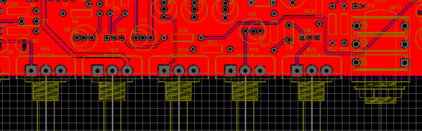
The only problem with a lot of this free software is it runs on Windows. I do sometimes run Windows, but I most often use Linux, so there is a certain attractiveness to a new breed of tools that run in the Web browser. In particular, I wanted to look briefly at two Web-based EDA tools: EasyEDA and MeowCAD. Both offer similar features: draw a schematic, populate a PCB, and download manufacturing files (that is, Gerber files). EasyEDA also offers SPICE simulation.

Continue reading “A Tale Of Two Browser PCB Tools”

Hack Your Own Analog Camera

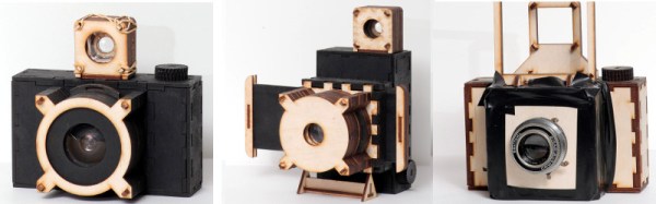
We remember making pinhole cameras as kids out of cigar boxes. The Focal Camera website wants to enable you to make sophisticated cameras from a selection of building blocks. We’re talking cameras with film, not digital cameras (although we wondered if you could mount an image sensor… but that’s another hack).

The modules do require access to a laser cutter, and you’ll need to scrounge or otherwise acquire things like mirrors and lenses. The site has advice on how to hack things like first surface mirrors out of cheap items like acrylic mirrors.

The intent is to be able to build up your own cameras from the modules. They do have a pinhole camera, in case you are nostalgic, but you could also build SLRs, large format cameras, or even stereo cameras. Not all the modules are ready yet, but there are several example cameras and pictures taken with them on the site. Like most building blocks, the real treat will be when users begin to combine them in unexpected ways.

Continue reading “Hack Your Own Analog Camera”

Learning Verilog For FPGAs: Flip Flops

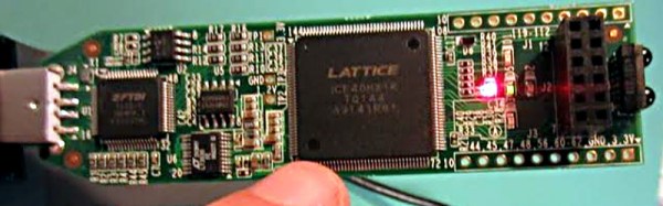
Last time I talked about how to create an adder in Verilog with an eye to putting it into a Lattice iCEstick board. The adder is a combinatorial circuit and didn’t use a clock. This time, we’ll finish the demo design and add two clocked elements: a latch that remembers if the adder has ever generated a carry and also some counters to divide the 12 MHz clock down to a half-second pulse to blink some of the onboard LEDs.

Why Clocks?

Clocks are an important part of practical digital design. Suppose you have a two input AND gate. Then imagine both inputs go from zero to one, which should take the output from zero to one, also. On paper, that seems reasonable, but in real life, the two signals might not arrive at the same time. So there’s some small period of time where the output is “wrong.” For a single gate, this probably isn’t a big deal since the delay is probably minuscule. But the errors will add up and in a more complex circuit it would be easy to get glitches while the inputs to combinatorial gates change with different delays.

Continue reading “Learning Verilog For FPGAs: Flip Flops”

Learning Verilog For FPGAs: The Tools And Building An Adder

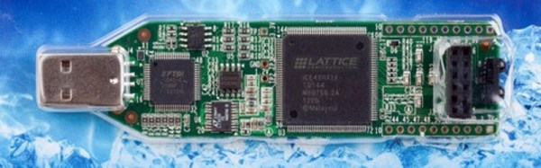
Over the last year we’ve had several posts about the Lattice Semiconductor iCEstick which is shown below. The board looks like an overgrown USB stick with no case, but it is really an FPGA development board. The specs are modest and there is a limited amount of I/O, but the price (about $22, depending on where you shop) is right. I’ve wanted to do a Verilog walk through video series for awhile, and decided this would be the right target platform. You can experiment with a real FPGA without breaking the bank.

In reality, you can learn a lot about FPGAs without ever using real hardware. As you’ll see, a lot of FPGA development occurs with simulated FPGAs that run on your PC. But if you are like me, blinking a virtual LED just isn’t as exciting as making a real one glow. However, for the first two examples I cover you don’t need any hardware beyond your computer. If you want to get ready, you can order an iCEstick and maybe it’ll arrive before Part III of this series if published.

Continue reading “Learning Verilog For FPGAs: The Tools And Building An Adder”

Color By Number 3D Printing Style

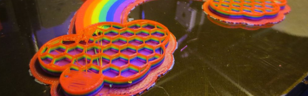
Remember paint-by-number kits? Your canvas has outlines with numbered regions that you paint with correspondingly numbered paints. When you are done, you’ve recreated the Mona Lisa. [KurtH3] uses a similar technique to coax multicolor prints from his 3D printer.

The technique isn’t general purpose, but it still is an interesting way to add some color to your usually monochrome prints. The idea is simple: You find a paint-by-number layout (apparently, you can find them with a Google search). Use your favorite method to get the outline into a CAD program. [KurtH3] doesn’t really get into the details about this, but some CAD programs will directly import images. Others will require you to trace in Inkscape (or a similar program) and convert to a vector format like DXF that the 3D CAD program can import.

Here’s the trick: instead of extruding the 2D image as one piece, you extrude the numeric regions to slightly different heights. Say you wanted to print a red, white, and blue flag to a thickness of about 5mm and you use 0.2mm layers. You could extrude the white part to 5mm, for example. Then the red parts could be extruded to 5.2mm (one layer higher) and the blue parts to 5.4mm. You could extend the idea to do multiple layers, although that will increase the surface roughness.

[KurtH3] pauses the print at the end of the layers to change filament, but we would probably edit the sliced G-Code to put pauses in the right places (for example, Repetier Host lets you put @pause in your file). You could also use software to split the G-Code as we’ve previously covered.  The resulting print, using our example, would be white from the bottom up but would have thin red and blue layers over the top in the right places. The few hundred microns difference from the white surface to the other colors means you won’t get a perfectly smooth surface, but a few hundred microns shouldn’t be too noticeable.

Continue reading “Color By Number 3D Printing Style”

Microcontroller Adjustment Of A DC To DC Converter

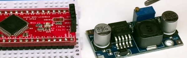
[Hugatry] wanted to replace the adjustment pot on an LM2596 buck converter with a microprocessor-controlled voltage. The regulator IC uses a divider to generate a 1.25V reference from the output. The pot is part of a divider circuit that sets the output voltage. For example, if the divider is 10:1, the controller will keep the output at 1.25V and, therefore, the output voltage will be 12.5V.

[Hugatry’s] strategy was to use a filtered PWM signal from a microcontroller to offset the 1.25V signal. By adding a small voltage to the control point, the output voltage would not need to rise as high as before to maintain the 1.25V reference. For example, adding 0.25V to the reference input would only require 1V, which corresponds to a 10V output.

The video has a nice view of a scope showing the relationship between the PWM duty cycle and the output voltage. Although he didn’t mention it, it struck us that since PWM is proportional to the supply voltage, the voltage on the microcontroller and PWM output stage probably needs to be fixed. That implies you couldn’t use the buck converter to directly power the microcontroller itself. Then again, what kind of microcontroller needs to adjust its own power supply?

Continue reading “Microcontroller Adjustment Of A DC To DC Converter”

Literal Breadboard Hack Forces It To Accept Dual Pin Headers

Usually when there is a clear demand for something, some entrepreneur will fill that demand. Unfortunately, no one seems to think there’s a need for a solderless breadboard product that can handle boards that have a dual row header. These devices have 0.1″ spacing in both directions, so while they will fit in a standard breadboard, the contacts will short out the adjacent pins on the device, which makes it worthless.

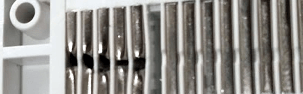
[Baz] needed to connect an RF24L01 module to a breadboard. Instead of connecting leads to the device or devising a breakout board, [Baz] actually hacked his breadboard. To make an area to plug in a dual row device, he took the breadboard apart, pulled the spring contacts, cut them, and then put them back in.

Of course, you have to make sure the cut is wide enough that the two parts of the spring won’t touch. It looks like [Baz] used a small screwdriver to help the springs keep their shape and cut them with simple diagonal cutters.

Continue reading “Literal Breadboard Hack Forces It To Accept Dual Pin Headers”