A Gameport Joystick To USB-MIDI Converter

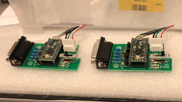
These days, live music performance often involves electronic synthesizers and computers rather than traditional instruments played by hand. To aid in his own performances, [alekappa] built a special interface to take signals from a joystick and convert them to MIDI messages carried over USB.
The build is simple and straightforward, using a Teensy LC to interface with a simple gameport joystick. With a smattering of simple components, it’s easy to read the outputs of the joystick with only a little debounce code needed to ensure the joystick’s buttons are read accurately. Similarly, analog axes are read using the analog-to-digital converters onboard the microcontroller.

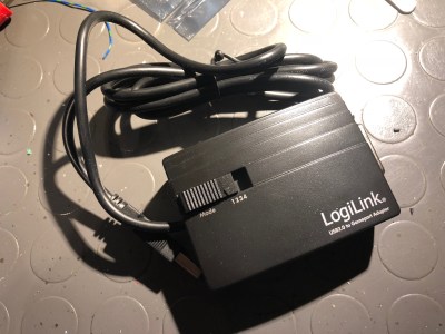
This data is then converted into control changes, note triggers and velocity levels and sent out over the Teensy LC’s USB interface. A mode switch enables changes to the system’s behaviour to be quickly made. The device is wrapped up in a convenient housing nabbed from an old Gameport-to-USB converter from many years ago.

It’s a neat project and we’re sure the joystick allows [alekappa] to add a new dimension to his performances on stage. We’ve seen other great MIDI controllers, too, from the knitted keyboard to the impressive Harmonicade. If you’ve got your own mad musical build under construction, don’t hesitate to drop us a line!

Remoticon 2021 // Joey Castillo Teaches Old LCDs New Tricks

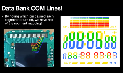
Segmented liquid crystal displays are considered quite an old and archaic display technology these days. They’re perhaps most familiar to us from their use in calculators and watches, where they still find regular application. [Joey Castillo] decided that he could get more out of these displays with a little tinkering, and rocked up to Remoticon 2021 to share his findings.

[Joey’s] talk is a great way to learn the skills needed to reverse engineer a typical segment LCD.
[Joey] got his start hacking on these displays via his Sensor Watch project –  a board swap for the venerable Casio F-91W wristwatch, with the project now available on CrowdSupply. It kits out the 33-year-old watch design with a modern, low-power ARM Cortex M0+ microcontroller running at 32 MHz that completely revolutionizes what the watch can do. Most importantly, however, it repurposes the watches original segmented monochrome LCD.

Segment LCDs are usually small monochrome devices made out of glass, that have the benefit of using very little power in their operation. They come with a fixed layout, which cannot be changed – so they’re often designed specifically for a given purpose. A calculator will have segments laid out to display numbers, often in the usual 7-segment fashion, while a watch may add dedicated segments for displaying things like “AM,” “PM,” or “ALARM.” Continue reading “Remoticon 2021 // Joey Castillo Teaches Old LCDs New Tricks” →

How To Get Your Diffraction Grating 3D Prints Right The First Time

Diffraction gratings are beautiful things, bending transmitted and reflected light and splitting it into its component wavelengths to create attractive iridescent rainbow patterns. It’s the same effect you see on the bottom of a CD!

You can 3D print a functional diffraction grating, too, with the right techniques, as it turns out! The average 3D printer can’t recreate the tiny-scaled patterns of a diffraction grating directly; a typical diffraction grating may have up to 1000 lines per mm. Instead, by 3D printing onto an existing diffraction grating, the print can pick up the texture on its base layer. It’s a great way to add iridescence and shine to a print.

We’ve seen similar work before, but the guide from [All3DP] goes into greater detail on how to get the effect to work just right. Getting the bed as close to perfectly level is key here, as is the first layer height. This is because the first layer of plastic has to meld perfectly with the diffraction grating to pick up the pattern. Too high and the grooves won’t transfer to the plastic, and too low, and it’s likely you’ll just melt the grating itself. Setting the Z-offset appropriately can help here.

Choosing the right bed temperature is also important to ensure the molten plastic is able to flow into the grooves of the grating. Again, the temperature at which the diffraction grating itself can survive is important to take into account; going above 90 degrees can be risky here. The guide also shows two methods of achieving the goal: one can either use an off-the-shelf grating, or one can prepare a no-longer-wanted CD into a suitable print surface.

Naturally, removing the print must be done delicately, lest one disturb the delicate structures key to generating the iridescent effect. [All3DP] recommends using a freezer to help separate the parts from the grating surface. It also bears noting that the print won’t survive excessive handling, as the grating structures will get damaged by physical touch.

It’s a great in-depth guide on how to get diffraction grating prints right. Meanwhile, consider diving deeper into the world of 3D printed optics!


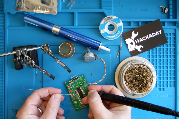
Ask Hackaday: What’s Your Worst Soldering Job?

Soldering! It’s the primary method for attaching one component to another in the world of electronics. Whether you’re free-forming a circuit, attaching connectors to cables, or populating a PCB, you’ll eventually find yourself doing some soldering, whether by hand, reflow, or maybe even a fancy wave soldering machine.

It’s a fundamental skill that nevertheless remains one of the biggest hurdles for newcomers to overcome when diving into the electronics hobby. Difficult jobs with tiny components or with large heat sinks can up the challenge for even well-practiced hands. Thus, today we ask the question: What’s your worst soldering job?
Continue reading “Ask Hackaday: What’s Your Worst Soldering Job?” →

Pulling Off A CRT Transplant Doesn’t Have To Be Tricky!

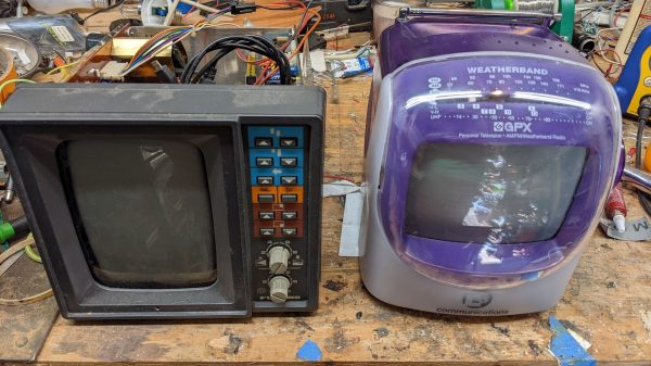
Whether it’s an engine swap in an old car or pulling a hard drive out of an old computer, we often find ourselves transplanting bits from one piece of hardware to another. [Emily Velasco] recently attempted this with a pair of CRTs, and came away with great success.

The donor was an old 1980s fishing sounder, which came complete with a rather fetching monochrome amber CRT display. [Emily]’s goal was to transplant this into the body of a early 2000s portable television. The displays were of a similar size and shape, though the Toshiba CRT from the 80s used a lot more glass in its construction.

The tube socket in the TV used to hook up the display matched the old CRT perfectly, so there were no hassles there. A bit of soldering was all that was needed to hook up the yoke, and [Emily] was ready to test. Amazingly, it powered up cleanly, displaying rolling amber static as you’d expect, given that analog television stations have been off the air for some time now.

After some perseverance, a VCR playing Mystic Pizza on VHS was able to deliver a video signal to the TV, proving that everything was working well. The next stage of the project is to get the television electronics to fit inside the 1980s fishing sounder housing, as it’s the more attractive of the two. Things were just built differently back in those days!

We’ve seen some other great vintage display swaps before, too. Video after the break.

Continue reading “Pulling Off A CRT Transplant Doesn’t Have To Be Tricky!” →

Coin Cell Eliminator Does More Than Save Batteries

Coin cells are useful things that allow us to run small electronic devices off a tiny power source. However, they don’t have a lot of capacity, and they can run out pretty quickly if you’re hitting them hard when developing a project. Thankfully, [bobricius] has just the tool to help.

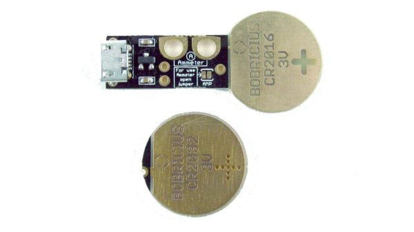
The device is simple – it’s a PCB sized just so to fit into a slot for a CR2016 or CR2032 coin cell. The standard board fits a CR2016 slot thanks to the thickness of the PCB, and a shim PCB can be used to allow the device to be used in a CR2032-sized slot instead.

It’s powered via a Micro USB connector, and has a small regulator on board to step down the 5 V supply to the requisite 3 V expected from a typical coin cell. [bobricius] also gave the device a neat additional feature – a pair of pads for easy attachment of multimeter current probes. Simply open the jumper on the board, hook up a pair of leads, and it’s easy to measure the current being drawn from the ersatz coin cell.

If you’re regularly developing low-power devices that use coin cells, this tool is one that could save a lot of mucking about in the lab. [bobricius] has them available on Tindie for those eager to get their hands on one. We’ve seen similar designs before too, albeit pursued in a different way!

Building A High-Capacity Linear Servo Actuator

Linear actuators are useful things, moving things in straight lines rather than annoying circles like so many motors. [Retsetman] recently built a linear servo actuator of his own design with accurate positional control.

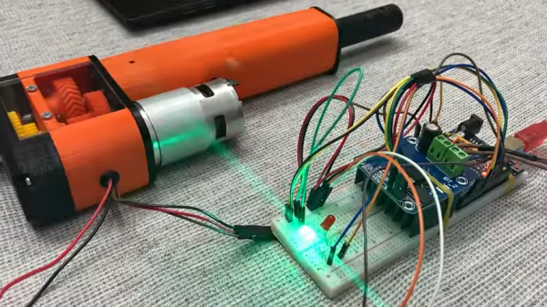
The design relies on a carriage that moves along a threaded rod, perhaps the most rudimentary design of linear actuator. A large brushed DC motor is used to turn the threaded rod through a 3D-printed 9:1 herringbone geartrain, shifting the actuator back and forth. End stop switches are used to disengage the motor to avoid damage to the mechanism. Feedback is via a ten-turn potentiometer driven off the output geartrain to match the range of the actuator to the rotational range of the pot.

The final build has a stroke of approximately 100 mm, and can lift and hold a 15 kg weight with ease. In a pull test, the actuator failed at a load just shy of 100 kg. If you’re looking for something smaller, though, you can try building a linear actuator out of old DVD drive parts instead. Video after the break.

Continue reading “Building A High-Capacity Linear Servo Actuator” →