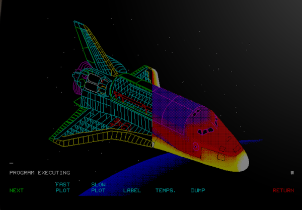
There are some things that leave indelible impressions in your memory. One of those things, for me, was a technical presentation in 1980 I attended — by calling in a lot of favors — a presentation by HP at what is now the Stennis Space Center. I was a student and it took a few phone calls to wrangle an invite but I wound up in a state-of-the-art conference room with a bunch of NASA engineers watching HP tell us about all their latest and greatest. Not that I could afford any of it, mind you. What really caught my imagination that day was the HP9845C, a color graphics computer with a roughly $40,000 price tag. That was twice the average US salary for 1980. Now, of course, you have a much better computer — or, rather, you probably have several much better computers including your phone. But if you want to relive those days, you can actually recreate the HP9845C’s 1980-vintage graphics glory using, of all things, a game emulator.
The Machine
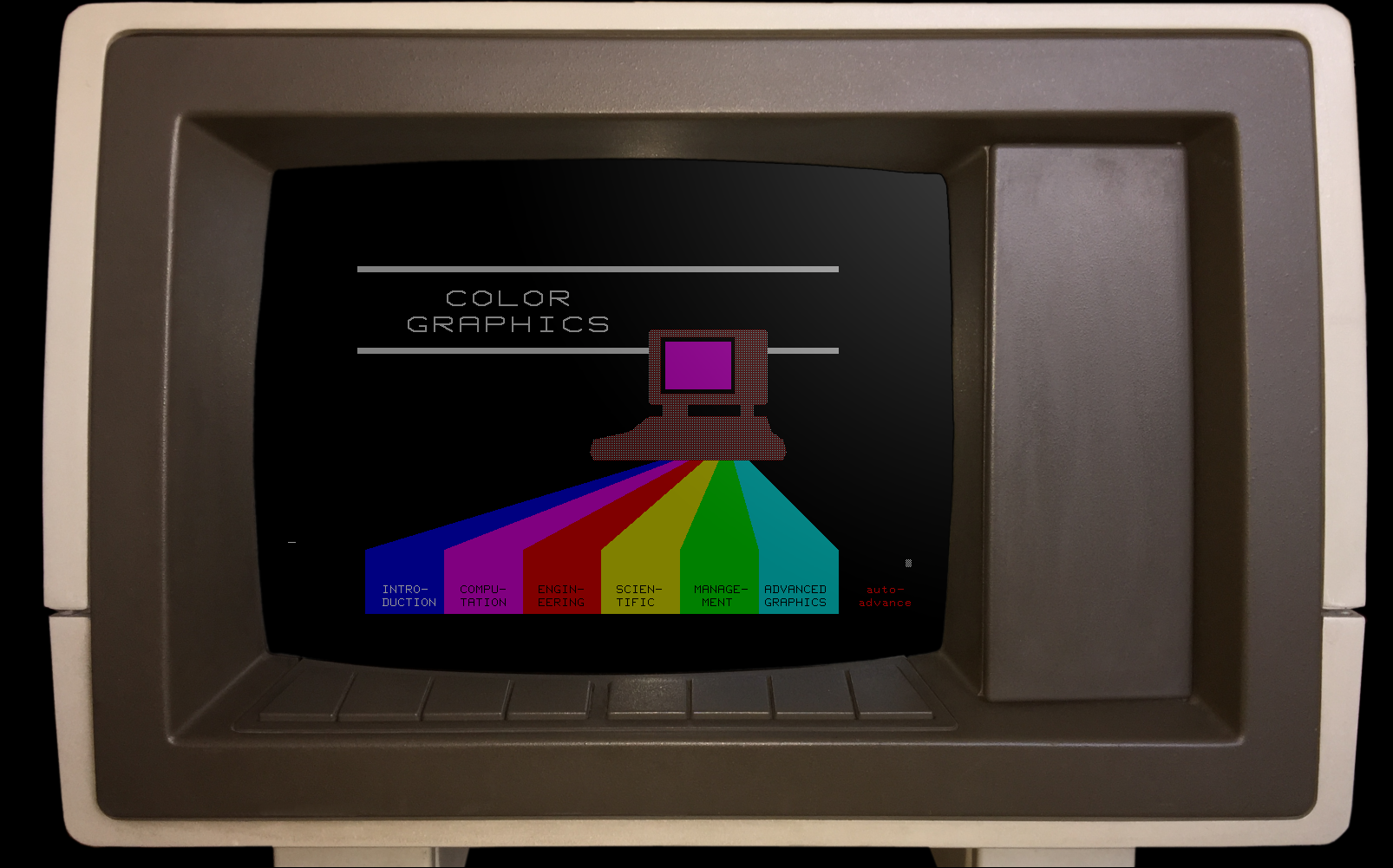
Keep in mind that the IBM PC was nearly two years away at this point and, even then, wouldn’t hold a candle to the HP9845C. Like many machines of its era, it ran BASIC natively — in fact, it used special microcode to run BASIC programs relatively quickly on its 16-bit 5.7 MHz CPU. The 560 x 455 pixel graphics system had its own CPU and you could max it out with a decadent 1.5 MB of RAM. (But not, alas, for $40,000 which got you — I think –128K or so.)
The widespread use of the computer mouse was still in the future, so the HP had that wonderful light pen. Mass storage was also no problem — there was a 217 kB tape drive and while earlier models had a second drive and a thermal printer optional, these were included in the color “C” model. Like HP calculators, you could slot in different ROMs for different purposes. There were other options such as a digitizer and even floppy discs.
Continue reading “Your Own Engineering Workstation, With Mame”