The I2C extender board on a white background, fully assembled, with two connectors and two indicator LEDs

Extenders And Translators For Your I2C Toolkit

If you’ve ever been laying out a network I2C devices inside a project box or throughout your robot’s body, you’ll probably know that I2C is not without its pitfalls. But for many of those pitfalls, there’s a handy chip you can use. [Roman Dvořák] from ThunderFly has experienced it on their drone building journeys, and that’s why they bring us two wonderful open source hardware boards: an I2C bus extender, and an I2C address translator.

The first board, an I2C bus extender, is based around the TCA4307 chip, and not only it lets you extend the bus further than it would normally go, it would also protect you. When the bus capacity is no longer handleable by your devices, or a particular misbehaving device gets the bus stuck, this chip will take care of it and dissipate your troubles. It will even let you know when your bus is wired up correctly, with a handy shine-through LED!

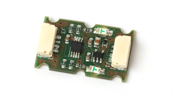
The second board is an I2C address translator. We’ve covered them before, but in short, address translators let you avoid I2C address conflicts while using multiple devices that share the same address. This particular module uses the LTC4317 chip, a common choice for such translation, and the board leaves no feature unimplemented. In the README, there’s quite a few pictures with examples of where this sensor proves mighty useful, too!

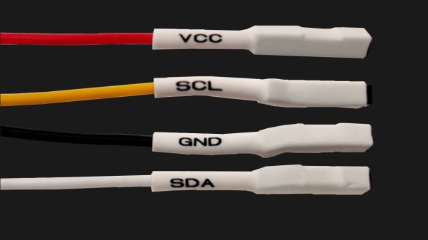
It appears that ThunderFly open sources a lot of their designs on GitHub, an effort that we salute. The designs are great to learn from, but if you’re just looking for turn-key hardware, you can get both of these boards from their Tindie store. The cables they use have locking connectors, but as long as the pinout matches, you should be able to solder a JST-SH socket and add these modules to your QWIIC toolkit.

SatCat5: UART, SPI And I2C Via Ethernet With FPGA-Based Design

Arty A7-based prototype of SatCat5 with custom switch I/O board. (Credit: The Aerospace Corporation)

To the average microcontroller, Ethernet networks are quite a step up from the basic I2C, SPI and UART interfaces, requiring either a built-in Ethernet MAC or SPI-based MAC, with tedious translation between Ethernet and those other interfaces. Yet what if this translation could be done automatically and transparently?  This is what the SatCat5 FPGA-based project by [The Aerospace Corporation] aims to provide: a gateway akin to an unmanaged Ethernet switch that also supports those non-Ethernet links. Recently they answered a range of questions about the project on Hacker News.

The project name comes from the primary target audience: smallsat and cubesat developers, which is an area where being able to route more traffic over a common Ethernet-based bus is a major boon. The provided Xilinx Artix-7-based reference design (pictured) gives a good idea of how it can be used: it combines an Arty A7 development board with a custom PCB containing an Ethernet switch IC (SJA1105), TJA1100 transceiver, two RJ45 jacks and four PMOD connectors, here connected to two UARTs for bidirectional communication between them. Ethernet frame encapsulation is provided using the standard Serial Line Internet Protocol (SLIP), with more details covered in the FAQ. At a minimum an FPGA like a Lattice iCE40 is required, with an MCU capable of using the provided C++ libraries, or a custom implementation.

Thanks to [STR-Alorman] for the tip.

Hackaday Podcast Episode 260: KiCad 8, Two Weather Stations, And Multiple I2Cs

It’s a leap year, so Elliot and Dan put the extra day to good use tracking down all the hottest hacks from the past week and dorking out about them. There’s big news in the KiCad community, and we talked about all the new features along with some old woes. Great minds think alike, apparently, since two different e-ink weather stations made the cut this week, as did a floating oscilloscope, an automated film-developing tank, and some DIY solar panels.

We talked about a hacker who figured out that water makes a pretty good solar storage medium, and it’s cheaper than lithium, another who knows that a crappy lathe is better than no lathe, and what every hacker should know about Ethernet. Is there a future for room-temperature superconductors? Maybe it just depends on how cold the room is.


Grab a copy for yourself if you want to listen offline.

Continue reading “Hackaday Podcast Episode 260: KiCad 8, Two Weather Stations, And Multiple I2Cs”

A breadboard showing a tiny ESP32 board and two HMC5883L sensors connected to it on different pins

Avoid I2C Address Conflicts On ESP32 By Pin Muxing

Using hardware I2C on an ESP32? Do you need to connect multiple I2C devices with the same address? Normally, you wouldn’t be able to do that without extra parts, but on the ESP32, [BastelBaus] has found a nice hack — just connect your devices to different pins and slightly abuse the ESP32 GPIO muxing, no extra hardware required!

Initially, they tried separating SDA and SCL completely, and after a bit of tinkering, that’s worked out wonders! For this method, [BastelBaus] provides example Arduino code you could easily integrate into your project, and shows logic analyzer captures that demonstrate there’s barely any overhead. Later, they’ve also found out that you could multiplex only one of the pins, specifically, SDA, having the SCL line be common! As far as we see, this could also work out with split SCL, but do let us know if that doesn’t sound right.

Typically, such a problem is solved with an I2C multiplexer, and we’ve highlighted projects with them before. However, this simple method could also work on chips like the RP2040 or even the Raspberry Pi 4 — just a bit more limited, since the GPIO muxing for I2C has less available ports! Also, if you’re not using a chip with such a comfortable GPIO mux and you must use devices with overlapping addresses, check out the comment section under our I2C ecosystem article – there’s a fair few other methods you can use. And, if this method ever malfunctions for you, there’s a bunch of very straightforward ways you could debug your bus!

Displays We Love Hacking: SPI And I2C

I’ve talked about HD44780 displays before – they’ve been a mainstay of microcontroller projects for literal decades. In the modern hobbyist world, there’s an elephant in the room – the sheer variety of I2C and SPI displays you can buy. They’re all so different, some are LCD and some are OLED, some have a touchscreen layer and some don’t, some come on breakouts and some are a bare panel. No matter which one you pick, there are things you deserve to know.

These displays are exceptionally microcontroller-friendly, they require hardly any GPIOs, or none extra if you already use I2C. They’re also unbelievably cheap, and so tiny that you can comfortably add one even if you’re hurting for space. Sure, they require more RAM and a more sophisticated software library than HD44780, but with modern microcontrollers, this is no problem at all. As a result, you will see them in almost every project under the sun.

What do you need for those? What are the requirements to operate one? What kind of tricks can you use with them? Let’s go through the main aspects.

Continue reading “Displays We Love Hacking: SPI And I2C”

Flip The Switch On This I2C Controlled USB Hub

You’ve probably seen USB hubs with physical switches for each port, they provide a handy way to cut the power to individual devices, but only if you’re close enough to flip them. They won’t do you much good if you want to pull the plug on a USB gadget remotely.

That’s why [Jim Heaney] created the I2C-USB-Hub. The device takes your standard USB 2.0 hub circuit, and adds in a MT9700 P-MOSFET load switch for each port. The enable pin on each of these switches is in turn connected to one of the output pins of a PCA9557PW I2C I/O chip. That means controlling each port is as easy as sending the proper sequence of bits over the wire, though [Jim] says he does plan on writing up an Arduino library to make flipping the digital switches a little more user friendly.

Since the 8-bit chip had a few extra pins left over, [Jim] wired one up to serve as a master control for the LED indicator lights on the PCB. Another is used to adjust the current limit on the MT9700 between 500 mA and 1 A.

While naturally we’re big fans of spinning up your own hardware here at Hackaday, we’ve also seen similar results achieved by modifying an off-the-shelf USB hub.

Four jumper wires with white heatshrink on them, labelled VCC, SCL, SDA and GND

Three Pitfalls In I2C Everyone Wishes Weren’t There

The best part of I2C is that it is a bus that is available just about anywhere, covering a vast ecosystem of devices that offer it as a hardware-defined interface, while being uncomplicated enough that it can also be implemented purely in software on plain GPIO pins. Despite this popularity, I2C is one of those famous informal standards that feature a couple of popular implementations, while leaving many of the details such as exact timing, bus capacitance and other tedious details to the poor sod doing the product development. Thus it is that we end up with articles such as a recent one on the tongue-twisting [pair of pared pears] blog, covering issues found while implementing an I2C slave.

As with any shared bus, whether multi-master or not, figuring out when the bus is clear is a fun topic, yet one which can cause endless headaches. One issue here comes from a feature that the SMBus version of I2C calls quick read/write. This allows for the rapid transfer of some data. Still, depending on the data returned by the slave, it may appear to the master that nothing is happening yet, since SDA is being held low by the slave until the stop condition, essentially locking the bus.

I2C hold times example.

Where things get even more exciting comes generally in the form of what logic analyzers love to traumatically call a ‘spurious start/stop condition’. This refers to the behavior of SDA and SCL, with SDA going low before SCL indicating an error. This can occur due to a hold time that’s too low, causing other devices on the bus to miss the transition. Here SMBus defines a transition time of 300 ns, while I2C calls for 0 seconds, but it’s now suggested to delay calling a start/stop condition until a delay of 300 ns has passed. Essentially, it would seem that implementing a hold time is the way forward until evidence to the contrary appears.

The third pitfall pertains to the higher-speed modes of I2C, including Fast-Mode (FM) and Fast-Mode Plus (FM+). Backward compatibility with these higher speed versions is absent to spotty. Although FM+ (introduced by NXP in 2007) is supposed to be backward compatible with slower speeds, effectively the timing requirement differences between the FM+ and FM standards are too large to compensate for. At least in the current versions of the standards, but one of the joys of I2C is that there’s always another new set of revisions to look forward to.