On yet another one of those long, pointless road trips that seemed to punctuate my life starting when I got my license, I was plying the roads somewhere in eastern Pennsylvania with a friend. He told me that on long trips he’d often relieve the boredom by finding another car from the same state as his destination, and then just follow it. I wasn’t sure then how staring at the same car, hour after hour, mile after mile, would do anything but increase the boredom while making you look sort of creepy, but it seemed to work for him.
What works for college kids in cars also works for long-haul truckers, and the concept of a convoy has long been a fact of life on the road and a part of popular culture. Hardly a trip on the US Interstate goes by without seeing a least two truckers traveling in close formation, partly for companionship and mutual support but also for economic reasons. And now technology is poised to take convoying to the next level, as platooning becomes yet another way to automate the freight.
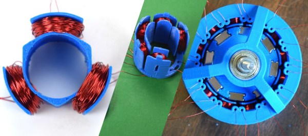
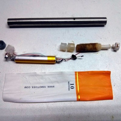
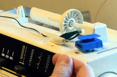 The fun of this project is copying the components found in the commercial hardware and varying the windings and coil count to see how it affects performance. If you have ever wound magnet wire around a nail to make an electromagnet, you know it is tedious work so check out their 3D printed coil holder with an embedded magnet to trigger a winding count and a socket to fit on a sewing machine bobbin winder. If you are going to make a bunch of coils, this is going to save headaches and wrist tendons.