It’s a simple goal: build a waterproof box full of environmental sensors that can run continuously for the next century. OK, so maybe it’s not exactly “simple”. But whatever you want to call this epic quest to study and record the planet we call home, [sciencedude1990] has decided to make his mission part of the 2019 Hackaday Prize.
The end goal might be pretty lofty, but we think you’ll agree that the implementation keeps the complexity down to a minimum. Which is important if these solar-powered sensor nodes are to have any chance of going the distance. A number of design decisions have been made with longevity in mind, such as replacing lithium ion batteries that are only good for a few hundred recharge cycles with supercapacitors which should add a handful of zeros to that number.
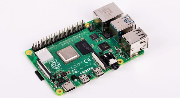
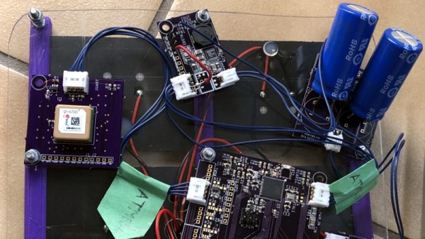
 At the most basic level, each node in the system consists of photovoltaic panels, the supercapacitors, and a “motherboard” based on the ATmega256RFR2. This single-chip solution provides not only an AVR microcontroller with ample processing power for the task at hand, but an integrated 2.4 GHz radio for uploading data to a local base station. [sciencedude1990] has added a LSM303 accelerometer and magnetometer to the board, but the real functionality comes from external “accessory” boards.
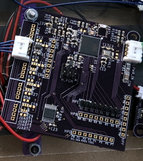
Along the side of the main board there’s a row of ports for external sensors, each connected to the ATmega through a UART multiplexer. To help control energy consumption, each external sensor has its own dedicated load switch; the firmware doesn’t power up the external sensors until they’re needed, and even then, only if there’s enough power in the supercapacitors to do so safely. Right now [sciencedude1990] only has a GPS module designed to plug into the main board, but we’re very interested in seeing what else he (and perhaps even the community) comes up with.


![An American-made Windsor chair from the turn of the 19th century. Los Angeles County Museum of Art [Public domain]](https://hackaday.com/wp-content/uploads/2019/05/Windsor_Arm_Chair_LACMA_54.80.jpg)