Big companies spend small fortunes on making sure their computers stay running and that they can be repaired quickly in an emergency. You wouldn’t expect an emergency repair on an Amiga 2000, though. [RETR-O-MAT] bought an Amiga 2000 that did boot, but was known to have a leaky battery on the motherboard. He wanted to rush to replace the battery before the leakage caused serious damage. You can see all this in the video below.
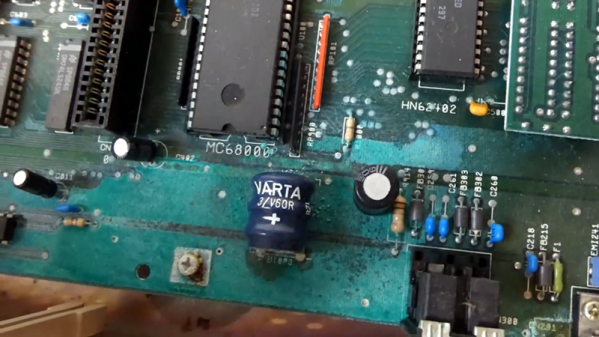
The computer looked lightly used over its 32-year lifespan, even when the case came off. The battery corrosion was evident, though. Even the bolt holding down the motherboard was clearly corroded from the leaking battery, causing it to be very difficult to remove.
The battery leakage also made unsoldering the battery a challenge. Several chips and sockets — including the CPU — were affected, so they had to come out. You can see a nice demonstration of the “old screwdriver trick” which might be eye-opening if you’ve only worked with SMD chips.
Even if you don’t care much about the Amiga 2000, it is interesting to see inside an old computer like this and note the differences — and similarities — to modern designs. The video is as much a tear down as it is a repair story. It also might be useful if you ever face having to tear out a leaky battery on any piece of gear. Continue reading “Amiga 2000 Emergency Repair”
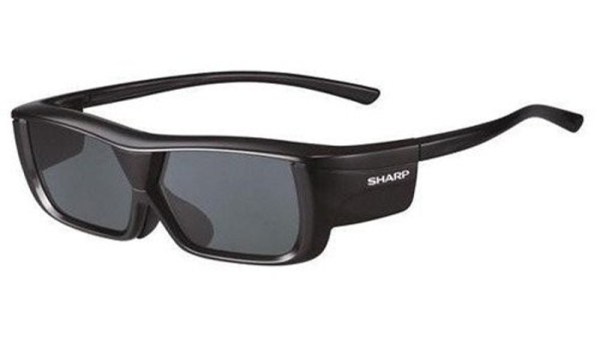
 Of course, once everyone had seen the film with the blue aliens and tried a few other titles on their new toy, they grew tired of headaches, nausea, and half-brightness. The glasses gathered dust, and the fancy 3D telly never ventured beyond two dimensions again. Except for [Bobricius’s] glasses, that is, for he’s levered out the 3D driver electronics and replaced them with a tiny SOIC-8 solar cell. Light hits the cell, the LCD gets a charge and darkens, no light and they remain transparent. Similar to welding goggles — though they usually use a battery. It’s unclear whether they can get a little too dark on a really bright day and whether they are something akin to