Microcontroller Adjustment Of A DC To DC Converter

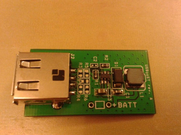
[Hugatry] wanted to replace the adjustment pot on an LM2596 buck converter with a microprocessor-controlled voltage. The regulator IC uses a divider to generate a 1.25V reference from the output. The pot is part of a divider circuit that sets the output voltage. For example, if the divider is 10:1, the controller will keep the output at 1.25V and, therefore, the output voltage will be 12.5V.

[Hugatry’s] strategy was to use a filtered PWM signal from a microcontroller to offset the 1.25V signal. By adding a small voltage to the control point, the output voltage would not need to rise as high as before to maintain the 1.25V reference. For example, adding 0.25V to the reference input would only require 1V, which corresponds to a 10V output.

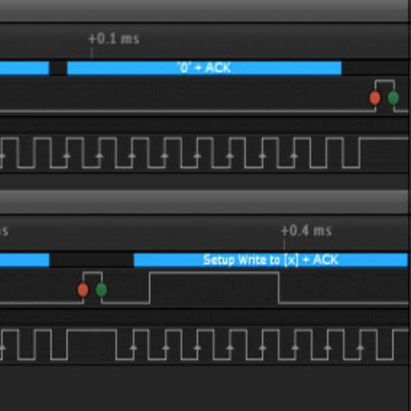
The video has a nice view of a scope showing the relationship between the PWM duty cycle and the output voltage. Although he didn’t mention it, it struck us that since PWM is proportional to the supply voltage, the voltage on the microcontroller and PWM output stage probably needs to be fixed. That implies you couldn’t use the buck converter to directly power the microcontroller itself. Then again, what kind of microcontroller needs to adjust its own power supply?

Continue reading “Microcontroller Adjustment Of A DC To DC Converter”

PeriUSBoost: A USB Battery Charger

PeriUSBoost: A DIY USB Battery Pack

If you travel often, use your mobile devices a lot, or run questionable ROMs on your phone, you likely have an external USB battery pack. These handy devices let you give a phone, tablet, or USB powered air humidifier (yes, those exist) some extra juice.

[Pedro]’s PeriUSBoost is a DIY phone charging solution. It’s a switching regulator that can boost battery voltages up to the 5 volt USB standard. This is accomplished using the LTC3426, a DC/DC converter with a built in switching element. The IC is a tiny SOT-23 package, and requires a few external passives work.

One interesting detail of USB charging is the resistor configuration on the USB data lines. These tell the device how much current can be drawn from the charger. For this device, the resistors are chosen to set the charge current to 0.5 A.

While a 0.5 A charge current isn’t exactly fast, it does allow for charging off AA batteries. [Pedro]’s testing resulted in a fully charged phone off of two AA batteries, but they did get a bit toasty while powering the device. It might not be the best device to stick in your pocket, but it gets the job done.

Boost Peak Power Tracking Battery Charger

[Rusdy] is building a solar charger for his electric bike, and quickly realized the lithium cells in his bike wouldn’t work well with the most common charge controllers out there. Solar cells have an IV curve, of course, and this changes with the amount of sunlight, requiring some conversion circuitry. Most of the charge controllers out there operate in buck mode, but the commercial boost mode converters [Rusdy] needed for his 36V battery are pricey as all get out. What was [Rusdy] to do? Build his own Boost MPPT solar charger, of course.

The circuit used for the charge circuit is fairly similar to a boost converter, with a little bit of logic required to get the maximum power out of the solar cells. [Rusdy] had an Arduino lying around, so that took care of the logic, and by sampling the voltage and current with the analog pins, he can turn a MOSFET on and off to get the most out of his solar cells.

The finished product works perfectly with an efficiency greater than 87%. Charging current and the final trickle charge is adjustable through software, allowing [Rusdy] to get the most out of his solar panels and electric bike. The board itself is just a prototype and could use a layout revision, but we’ve got to hand it to him for cloning a >$300 charge controller with an Arduino and a few scraps in a part drawer.


Minty Boost, AA Based USB Charger

Limor a.k.a. Ladyada has been a long standing staple in the Hack-A-Day community and we were more than happy to hear about her latest project. The Minty Boost is an improvement on the idea of building a battery powered USB charger. Most designs (including ours) use a 7805 linear regulator with a 9V battery. Even in the best case the regulator is only about 60% efficient which means you’re losing at least 1/3 of the power to heat. Limor’s design is a much more efficient boost converter design and uses far more common (and rechargeable) AA batteries. She’s got a thorough write up on how to build the converter in an Altoids gum tin. The end result is 82% efficient and can effectively double the play time of a video iPod.

The guide doesn’t end there. Limor actually wrote this as a demonstration on what goes into a making a kittable project. She covers the entire process from component selection, to mass PCB production, to what her final cost break down is. The guide is full of pictures thanks to some good planning as well. Of course the most interesting thing we learned from the guide is this: despite using the tins all the time, Limor finds the taste of Altoids gum disgusting.

[The guide is on her site, but we’re linking to the version on Instructables since we’ve managed to DDOS her site in the past… by announcing that her site was back online.]

Continue reading “Minty Boost, AA Based USB Charger”

A 3D-printed talking milk jug with a speech bubble that says 'glug'.

Talking Milk Jug Says Glug-Glug-Glug

Children can be a great source of daily inspiration, especially when they are just beginning to speak in full sentences and starting to let their little personalities show.

The innards of the milk jug. A sound module with SD card, a tilt switch, a boost converter, and so on. [Franklinstein] has the cutest toddler, and she loves her toy espresso machine, especially the little milk carton that came with it. Well, one day, Daddy made a glug-glug sound that delighted her, and he was inspired to build an entirely new milk jug that would make that special sound whenever it was turned over.

In order to keep the build relatively simple, [Franklinstein] used a sound module with an SD card and a tilt switch to activate it. There’s not much else to the build, really — just the usual suspects like a boost converter, a charging module, and a speaker, of course. In case you couldn’t tell, the enclosure and the internal skid that the electronics assemble onto are 3D printed.

This is really cute, and [Franklinstein]’s daughter seems to love it. Everything is available, including some nice instructions if you want to make one of your own. Be sure to check out the neat build video after the break.

The things we do for kids. Seriously.

Continue reading “Talking Milk Jug Says Glug-Glug-Glug”

Original Game Boy Gets Display “Upgrade”

Before LCD and LED screens were ubiquitous, there was a time when the cathode ray tube (CRT) was essentially the only game in town. Even into the early 2000s, CRTs were everywhere and continuously getting upgrades, with the last consumer displays even having a semi-flat option. Their size and weight was still a major problem, though, but for a long time they were cutting edge. Wanting to go back to this time with their original Game Boy, [James Channel] went about replacing their Game Boy screen with a CRT.

The CRT itself is salvaged from an old video conferencing system and while it’s never been used before, it wasn’t recently made. To get the proper video inputs for this old display, the Game Boy needed to be converted to LCD first, as some of these modules have video output that can be fed to other displays. Providing the display with power was another challenge, requiring a separate boost converter to get 12V from the Game Boy’s 6V supply. After getting everything wired up a few adjustments needed to be made, and with that the CRT is up and running.

Unfortunately, there was a major speed bump in this process when [James Channel]’s method of automatically switching the display to the CRT let the magic smoke out of the Game Boy’s processor. But he was able to grab a replacement CPU from a Super Game Boy, hack together a case, and fix the problem with the automatic video switcher. Everything now is in working order for a near-perfect retro display upgrade. If you’d like to do this without harming any original hardware, we’ve seen a similar build based on the ESP32 instead.

Continue reading “Original Game Boy Gets Display “Upgrade””

Turning An ATX PSU Into A Variable Bench Supply

Bench power supplies can sometimes be frustratingly expensive and also kind of limited. If you’re enterprising and creative, though, you can create your own bench supply with tons of features, and it doesn’t have to break the bank either. Do what [Maker Y] did—grab an ATX supply and get building!

ATX power supplies work as a great basis for a bench power supply. They have 12 volt, 3.3 volt, and 5 volt rails, and they can supply a ton of current for whatever you might need. [Maker Y] decided to break out these rails on banana plugs for ease of access, and fused them for safety, too. But the build doesn’t stop there. [Maker Y] also added a buck-boost converter to provide a variable voltage output from 1 to 30 volts for added flexibility. As a nice final touch, the rig also features a pair of USB A ports compatible with Quick Charge 3.0, for keeping smart devices charged while working in the lab.

[Caelestis Workshop] also designed a fully enclosed version if you prefer that style. Check it out on Instructables.

No matter which way you go, it’s a pretty simple build, with a bunch of off-the-shelf parts tossed together in a 3D printed housing. Ultimately, though, it’s got more functionality than a lot of cheap off-the-shelf bench supplies. You can build it just about anywhere on Earth where you can get cheap eBay parts via post. Continue reading “Turning An ATX PSU Into A Variable Bench Supply”