While 3D printing is now well on its way to becoming “boring” in the same way that a table saw or lathe is, there was a time when the media and even some early adopters would have told you that the average desktop 3D printer was perhaps only a few decades behind the kind of replicator technology we saw on the Enterprise. But as the availability of these machines increased and more people got to see one up close, reality sunk in pretty quickly.
Many have dismissed the technology as little more than a novelty, and even within the 3D printing community itself there’s a feeling that most printers are used for little more than producing “dust collectors”. Some would see this attitude as disheartening, but the hackers over at [Gear Down For What?] see it as a challenge. They’ve made it their mission to push printed parts to increasingly ridiculous heights to show just what the technology is capable of, and in their latest entry, set out to push a pair of 3D printed gearboxes to failure.
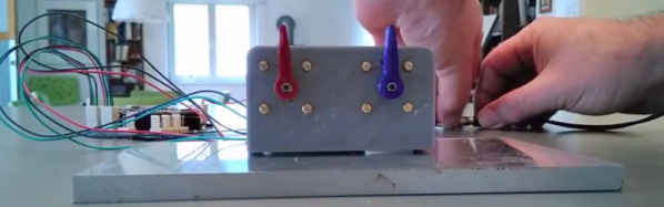
The video starts out with a head to head challenge between two of their self-designed gearboxes. As they were spun up with battery powered drills, the smaller of the two quickly gave up the ghost, stripping out at 228 lbs. The victor of the first round then went on to pull a static load, only to eventually max out the scale at an impressive 680 lbs.
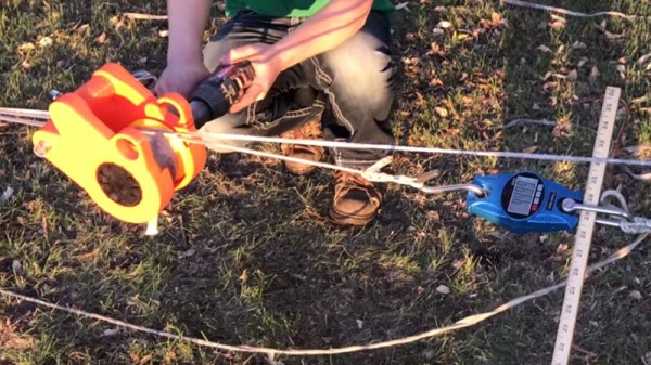
The gearbox may have defeated the scale, but the goal of the experiment was to run it to failure. By rigging up a compound pulley arrangement, they were able to double the amount of force their scale could detect. With this increased capacity the gearbox was then run up to an astonishing 1,000 lbs before it started to slip.
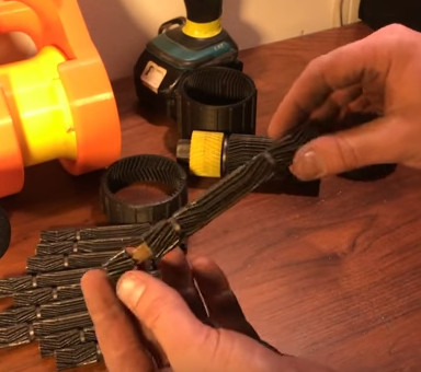
 But perhaps the most impressive: after they got the gearbox disassembled, it was discovered that only a single planet gear out of the ten had broken. Even then, judging by how the gear sheared, the issue was more likely due to poor layer adhesion during printing than from stress alone. No gears were stripped, and in fact no visible damage was seen anywhere in the mechanism. The team is currently unable to explain the failure, other than to say that the stresses may have been so great that the plastic deformed enough that the gears were no longer meshed tightly.
This isn’t the first time we’ve checked in with the team at [Gear Down For What?], just a few months ago they impressed us by lifting an anvil with one of their printed mechanisms. They’re also not the only ones curious to find out just how far 3D printed plastic can go.
Continue reading “Stripping 3D Printed Gears For Science” →