[Yingtao Zeng], [Qing Yang], and [Jun Li], a.k.a. the [UnicornTeam], developed the cheapest way so far to hack a passive keyless entry system, as found on some cars: around $22 in parts, give or take a buck. But that’s not all, they manage to increase the previous known effective range of this type of attack from 100 m to around 320 m. They gave a talk at HITB Amsterdam, a couple of weeks ago, and shown their results.
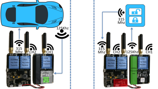
The attack in its essence is not new, and it’s basically just creating a range extender for the keyfob. One radio stays near the car, the other near the car key, and the two radios relay the signals coming from the car to the keyfob and vice-versa. This version of the hack stands out in that the [UnicornTeam] reverse engineered and decoded the keyless entry system signals, produced by NXP, so they can send the decoded signals via any channel of their choice. The only constraint, from what we could tell, it’s the transmission timeout. It all has to happen within 27 ms. You could almost pull this off over Internet instead of radio.
The actual keycode is not cracked, like in a HiTag2 attack. It’s not like hacking a rolling key keyfob either. The signals are just sniffed, decoded and relayed between the two devices.
A suggested fix from the researchers is to decrease this 27 ms timeout. If it is short enough, at least the distance for these types of attacks is reduced. Even if that could eventually mitigate or reduce the impact of an attack on new cars, old cars are still at risk. We suggest that the passive keyless system is broken from the get-go: allowing the keyfob to open and start your car without any user interaction is asking for it. Are car drivers really so lazy that they can’t press a button to unlock their car? Anyway, if you’re stuck with one of these systems, it looks like the only sure fallback is the tinfoil hat. For the keyfob, of course.
[via Wired]