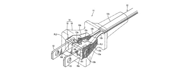
USB C allows data transfer, but also has provisions for transferring data related to power distribution. Of course, where there is data, there is a need to snoop on data for troubleshooting or reverse engineering. That’s the idea behind the open source Type-C/PD Analyzer.
Battletech Case Mod Displays Awesome Woodwork, Hides Hacks
[S.PiC] has been working on a computer case styled to look like the Vulture mech from Battletech. We’re not sure if his serious faced cat approves or not, but we do.
The case is made from artfully cut plywood. We kind of hope he keeps the wood aesthetic. However, that would be getting dangerously close to steampunk. So perhaps a matching paint job at the end will do. In some of the videos we can how he’s cleverly incorporated the computer’s components into the design of the case. For example, the black mesh on the front actually hides the computer’s power supply intake fan.
The computer inside is a small micro-itx formfactor one. Added as peripherals to it [S.Pic] has pulled out the hacker-electronics-tricks bible. From hand soldered LED grids to repurposed Nokia LCD screens, he has it all. In one video we can even see the turret of the mech rotating under its own power.
It looks like the build still has a few more steps before completion, but it’s already impressive enough to be gladly worth the useful table space consumed on any hacker’s desk. Video after the break.
Continue reading “Battletech Case Mod Displays Awesome Woodwork, Hides Hacks”
DIY Vein Finder Shows You Where To Stick It
Everyone who’s donated blood, gotten an intravenous (IV) line put in, or has taken a blood test knows that little bit of anxiety before the needle goes in. Will this be a one stick operation, or will the phlebotomist do their impression of drilling for oil while trying to find a vein? Some of us are blessed with easy to find blood vessels. Others end up walking out looking like they’ve been in a fight with a needle.
[Alex’s] wife girlfriend is a nurse who’s had trouble finding veins in the past. [Alex] is an automotive engineer by trade, more acquainted with oil lines than veins and arteries. While he couldn’t help her himself, [Alex] designed this 3D printed vein finder to help his wife girlfriend out at work. He started by studying devices on the market. Products like Veinlite use LEDs to illuminate the skin. Essentially these products are a string of LEDs and a battery. They are patented, FDA approved, and will set you back between $188 and $549 USD. [Alex] and his wife girlfriend couldn’t afford that kind of cost, so he built his own. Continue reading “DIY Vein Finder Shows You Where To Stick It”
Hackaday’s Fun With International Mains Plugs And Sockets
When we recently covered the topic of high voltage safety with respect to mains powered equipment, we attracted a huge number of your comments but left out a key piece of the puzzle. We take our mains plugs and sockets for granted as part of the everyday background of our lives, but have we ever considered them in detail? Their various features, and their astonishing and sometimes baffling diversity across the world.
When you announce that you are going to talk in detail about global mains connectors, it is difficult not to have an air of Sheldon Cooper’s Fun With Flags about you. But jokes and the lack of a co-starring Mayim Bialik aside, there is a tale to be told about their history and diversity, and there are also lessons to be taken on board about their safety. Continue reading “Hackaday’s Fun With International Mains Plugs And Sockets”
Beautiful Kegerator, Built The Hard Way
[Luke] brews his own beer. And like all beer brewers, he discovered that the worst part of homebrewing is cleaning out all the bottles. Time for a kegging system! And that means, time for a kegerator to keep the brew cold.
Normal kegerators are just a few holes drilled in an appropriate refrigerator. Most fridges have a step in the back where the compressor lives, which makes kegs an awkward fit, so [Luke] decided to build his own refrigerator.
He used beautiful wood and plenty of insulation. He failed, though, because he succumbed to the lure of the Peltier cooler. If there’s one problem with Peltier projects, it’s building first and looking up the specs second. They never have enough cool-juice. To quote [Luke]:
“… a comment I had seen somewhere on the Internet began to sink in: all projects involving peltier devices ultimately end in disappointment.“
(Bolding and italics from the original.) But at least he learned about defrosting, and he had a nice wood-paneled fridge-box in the basement.
Rather than give up, he found a suitable donor fridge, ripped out its guts, and transplanted them into his homemade box. A beautiful tap head sitting on top completes the look. And of course, there’s an ESP8266 inside logging the temperature and controlling the compressor, with all the data pushed out over WiFi. Try doing that with your Faraday Cage metal fridge!
We’ve seen kegerator builds before. Some of our favorites include this one that has a motorized retracting tap tower, and one that’s built into the walls of the house.
It’s Time For Direct Metal 3D-Printing
It’s tough times for 3D-printing. Stratasys got burned on Makerbot, trustful backers got burned on the Peachy Printer meltdown, I burned my finger on a brand new hotend just yesterday, and that’s only the more recent events. In recent years more than a few startups embarked on the challenge of developing a piece of 3D printing technology that would make a difference. More colors, more materials, more reliable, bigger, faster, cheaper, easier to use. There was even a metal 3D printing startup, MatterFab, which pulled off a functional prototype of a low-cost metal-powder-laser-melting 3D printer, securing $13M in funding, and disappearing silently, poof.
This is just the children’s corner of the mall, and the grown-ups have really just begun pulling out their titanium credit cards. General Electric is on track to introduce 3D printed, FAA-approved fuel nozzles into its aircraft jet engines, Airbus is heading for 3D-printed, lightweight components and interior, and SpaceX has already sent rockets with 3D printed Main Oxidizer Valves (MOV) into orbit, aiming to make the SuperDraco the first fully 3D printed rocket engine. Direct metal 3D printing is transitioning from the experimental research phase to production, and it’s interesting to see how and why large industries, well, disrupt themselves.
Star Trek Material Science Is Finally Real: Transparent Wood
It’s not transparent aluminum, exactly, but it might be even better: transparent wood. Scientists at the University of Maryland have devised a way to remove all of its coloring, leaving behind an essentially clear piece of wood.
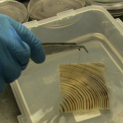 By boiling the block of wood in a NaOH and Na2SO chemical bath for a few hours the wood loses its lignin, which is gives wood its color. The major caveat here is that the lignin also gives wood strength; the colorless cellulose structure that remains is itself very fragile. The solution is to impregnate the transparent wood with an epoxy using about three vacuum cycles, which results in a composite that is stronger than the original wood.
There are some really interesting applications for this material. It does exhibit some haze so it is not as optimally transparent as glass but in cases where light and not vision is the goal — like architectural glass block — this is a winner. Anything traditionally build out of wood for its mechanical properties will be able to add an alpha color channel to the available options.
The next step is finding a way to scale up the process. At this point the process has only been successful on samples up to 1 centimeter thick. If you’re looking to build a starship out of this stuff in the meantime, your best bet is still transparent aluminum. We do still wonder if there’s a way to eliminate the need for epoxy, too.


