The Garden of Eden Creation Kit, or GECK, is the MacGuffan of Fallout 3 and the name of the modding tool for the same game. In the game, the GECK is a terraforming tool designed to turn the wasteland of Washington DC into its more natural form — an inhospitable swamp teeming with mosquitos.
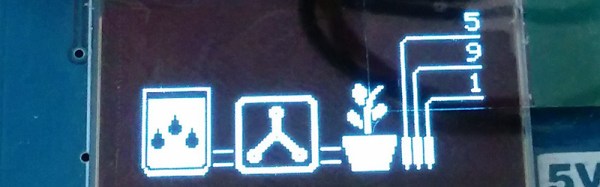
A device to automatically terraform any environment is improbable now as it was in Wrath of Khan, but a “Garden of Eden Kit” is still a really great name. For their Hackaday Prize entry, [atheros] is building a simplified version of this terraforming device. Instead of turning the Tidal Basin into potable water or turning a nebula into a verdant planet, [atheros]’s Garden of Eden Watering Kit turns empty potted plants into a lush harvest of herbs.
The device, like most home gardening solutions presented in this year’s Hackaday Prize, isn’t geared towards irrigating acres of crops. This is just a simple, small device meant to water a few herbs growing in a pot on a balcony. The hardware consists of a Teensy LC and a small OLED for command and control. A soil moisture sensor goes into each pot, and a few 12V peristaltic pumps water the plants from a bucket reservoir.
For the home gardener, it’s the perfect setup to grow some herbs, some chilis, or a cherry tomato plant that produces a year’s worth of tomatoes every week. It’s a great adaptation of off the shelf tech, and a great entry for the Hackaday Prize.
If you have been building electronic hardware for several decades, do you still have any projects from your distant past? Do they work? An audio amplifier perhaps, or a bench power supply.
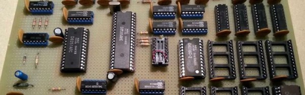
[Just4Fun] made a rather special computer in the 1980s, and it definitely still works. Describing it as “An 8085 single board computer with an EPROM emulator” though, does not convey just how special it is. This is not the modern sense of a single board computer with an SoC and a few support components. Instead it is a full system in the manner of the day in which processor, memory and peripherals are all separate components surrounded by 74 series glue logic. The whole system is wire-wrapped on a piece of perfboard and mounted very neatly in a rack. The EPROM emulator is a separate unit in a console case with hexadecimal keyboard and 7-segment display.
As the video below the break of an LED flashing demo shows, the EPROM emulator allows 8085 machine code to be entered byte by byte instead of having to be burned into a real EPROM.
[Just4Fun] leaves us with plans to replace the period EPROM emulator with a modern alternative, an EEPROM on a PCB designed to fit in the original bank of EPROM sockets. In this he suggests he might fit a bootloader and a BASIC interpreter, something entirely possible back in the day with conventional EPROMs, but probably not as cheaply.
For the last two years, Arduino LLC (the arduino.cc, Massimo one) and Arduino SRL (the arduino.org, Musto one) have been locked in battle over the ownership of the Arduino trademark. That fight is finally over. Announced at the New York Maker Faire today, “Arduino” will now go to Arduino Holding, the single point of distribution for new products, and a non-profit Arduino Foundation, responsible for the community and Arduino IDE.
Since early 2015, Arduino — not the Arduino community, but the organization known as Arduino — has been split in half. Arduino LLC sued Arduino SRL for trademark infringement. The case began when Arduino SRL, formerly Smart Projects SRL and manufacturers of the Arduino boards with a tiny map of Italy on the silk screen, began selling under the Arduino name. Arduino LLC, on the other hand, wanted to internationalize the brand and license production to other manufacturers.
While Arduino and Arduino have been tied up in court for the last few years, from the outside this has look like nothing else but petty bickering. Arduino SRL forked the Arduino IDE and bumped up the version number. Later, an update from SRL was pushed out to Amazon buyers telling them Arduino.org was the real Arduino. Resellers were in a tizzy, and for a time Maker Faires had two gigantic Arduino booths. No one knew what was going on.
All of this is now behind us. The open source hardware community’s greatest source of drama is now over.
I spoke with Massimo after the announcement, and although the groundwork is laid out, the specifics aren’t ready to be disclosed yet. There’s still a lot to work out, like what to do with the Arduino.org Github repo, which TLD will be used (we’re rooting for .org), support for the multitude of slightly different products released from both camps over the years, and finer points that aren’t publicly visible. In a few months, probably before the end of the year, we’ll get all the answers to this. Now, though, the Arduino wars are over. Arduino is dead, long live Arduino.
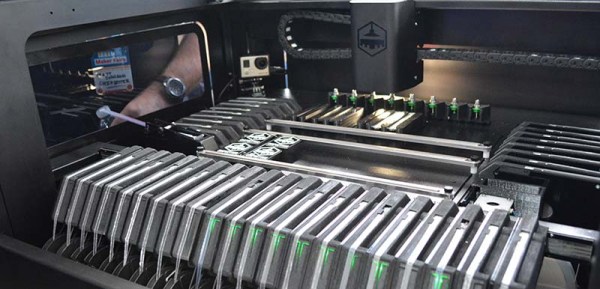
This weekend at Maker Faire, Chipsetter showed off their pick and place machine. It is, in my opinion, the first pick and place machine designed for hackerspaces, design labs, engineering departments, and prototypers in mind. It’s not designed to do everything, but it is designed to everything these places would need, and is much more affordable than the standard, low-end Chinese pick and place machine.
Inexpensive and DIY pick and place machines are familiar territory for us. A few years ago, we saw the Carbide Labs pick and place machine, a machine that allows you to put a board anywhere, pull chips out of tape, and place them on pasted pads. The Retro Populator is a pick and place machine that retrofits onto a 3d printer. The Firepick Delta, another Hackaday Prize project, takes a mini-factory to its logical conclusion and is capable of 3D printing, populating boards, dispensing paste, and creating its own circuit boards. All of these machines have one peculiarity: they are entirely unlike normal, standard, industrial pick and place machines.
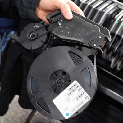
The Chipmaker feeder. Production versions of this feeder will be injection-molded plastic. This one is SLA nylon.
The idea of any startup is to build a minimum product, and the idea behind Chipsetter is to build a minimally viable tool. For their market, that means being able to place 0402 components (although it can do 0201, the team says the reliability of very small packages isn’t up to their standards), it means being able to shoot 1250 components per hour, and it must have inexpensive feeders to accept standard tape.
This is a complete departure from the spec sheet of a machine from Manncorp. For the ‘professional’ machines, a single feeder can cost hundreds of dollars. According to Chipsetter founder Alan Sawula, the feeders for this machine will hopefully, eventually cost about $50. That’s almost cheap enough to keep your parts on the feeder. A pro machine can handle 01005 components, but 0402 is good enough for most projects and products.
This is the closest I’ve seen to a pick and place machine designed to bridge the gap between contract manufacturers and hackerspaces. Most of the audience of Hackaday – at least as far as we’re aware – doesn’t have the funds to outsource all their manufacturing to a contract manufacturer. Most of the audience of Hackaday, though, or any hackerspace, could conceivably buy a Chipsetter. The Chipsetter isn’t designed to be the best, but when it comes to placing parts on paste, the best is overkill by a large margin.
The Chipsetter has a Kickstarter going right now. They’re about halfway funded, with a little more than three weeks to go. Right now, if you’re looking at pick and place machines, I’d highly suggest checking out the Chipsetter. It works, and with forty feeders it’s cheaper and more capable than the lowest priced ‘pro’ machines.
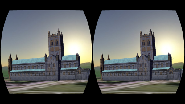
[WayneKeenan] wrote a proof-of-concept virtual reality system that used a Raspberry Pi and an Oculus Rift. It was about a thousand lines of Python and with a battery pack it was even portable. The problem was that the Pi was struggling to create the 3D views.
[Wayne] recently revisited the demo and found that just about everything has gotten better: the Pi 3 is faster, and the Python libraries have become better. He spent some time building a library — VR Zero — and then recreated the original demo in 80 more lines of Python. You can see a video, below.
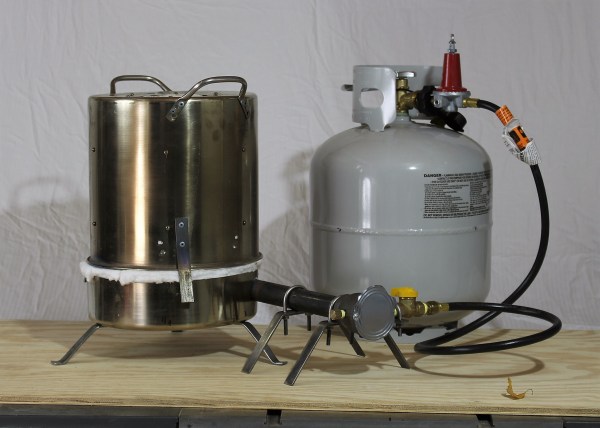
[Makercise] is getting ready for Maker Faire. One of the things he’d really like to do is some casting demonstrations. However, he has no desire to take his expensive and heavy electric kiln based foundry to Maker Faire. So, he made his own.
He got into metal casting during his excellent work on his Gingery lathe series. He started off by modeling his plan in Fusion 360. He’d use a 16qt cook pot turned upside down as the body for his foundry. The top would be lined with ceramic fiber insulation and the lid made out of foundry cement. He uses a Reil style burner, which he also modeled as an exercise. This design is light and even better, allows him to lift the top of foundry off, leaving the crucible completely exposed for easy removal.
All went well with the first iteration. He moved the handles from the top to the bottom of the pot and filled it with insulation. He built legs for the lid and made a nice refractory cement bowl on the bottom. However, when he fired it up the bowl completely cracked along with his crucible. The bowl from design flaw, the crucible from age.
A bit put off, but determined to continue, he moved forward in a different direction. The ceramic insulation was doing so well for the top of the foundry that he decided to get rid of the cement altogether and line the bottom with it as well. The lid, however, would be pretty bad for this, so he purchased another pot and cut the top portion of it off, giving him a steel bowl that matched the top.
The foundry fires up and has worked well through multiple pours. He made some interesting objects to hopefully sell at Makerfaire and to test the demonstrations he has planned. The final foundry weighs in at a mere 15lbs not including the fuel cylinder, which is pretty dang light. Video after the break.
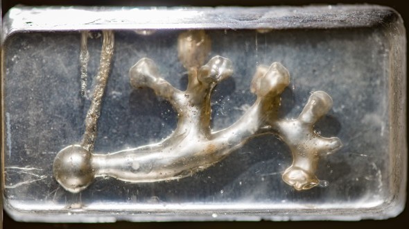
Citizen science isn’t limited to the nerd community. When medical professionals get a crazy idea, their options include filling out endless paperwork for human consent forms and grant applications, or hacking something together themselves. When [David Wartinger] noticed that far too many of his patients passed kidney stones while on vacation, riding rollercoasters, he had to test it out.
Without the benefit of his own kidney stones, he did the next best thing: 3D printed a model kidney, collected some urine, and tossed a few stones that he’d collected from patients into the trap. Then he and a colleague rode Big Thunder Mountain Railroad sixty times, holding the model in a backpack at kidney height.