In high voltage applications involving tens of thousands of volts, too often people think about the high voltage needed but don’t consider the current. This is especially so when part of the circuit that the charge travels through is an air gap, and the charge is in the form of ions. That’s a far cry from electrons flowing in copper wire or moving through resistors.
Consider the lifter. The lifter is a fun, lightweight flying machine. It consists of a thin wire and an aluminum foil skirt separated by an air gap. Apply 25kV volts across that air gap and it lifts into the air.


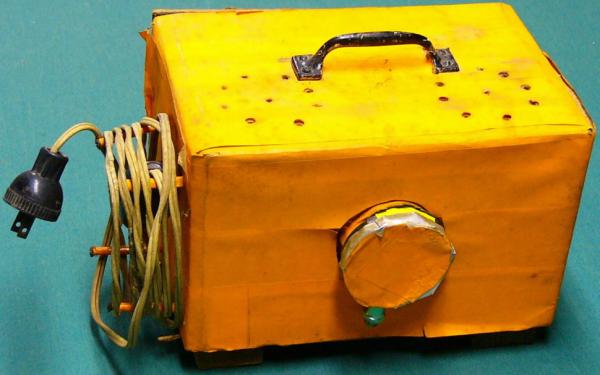
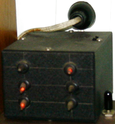
So you’d think that the small handheld Van de Graaff generator pictured below, that’s capable of 80kV, could power the lifter. However, like many high voltage applications, the lifter works by ionizing air, in this case ionizing air surrounding the thin wire resulting in a bluish corona. That sets off a chain of events that produces a downward flowing jet of air, commonly called ion wind, lifting the lifter upward.
Continue reading “High Voltage Please, But Don’t Forget The Current”