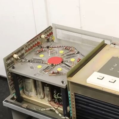
It’s Not A Leica, It’s A Lumix

There’s an old adage in photography that the best camera in the world is the one in your hand when the shot presents itself, but there’s no doubt that a better camera makes a difference to the quality of the final image. Among decent quality cameras the Leica rangefinder models have near cult-like status, but the problem is for would-be Leica owners that they carry eye-watering prices. [Cristian Băluță] approached this problem in s special way, by crafting a Leica-style body for a Panasonic Lumix camera. Given the technology relationship between the Japanese and German companies, we can see the appeal.

While the aesthetics of a Leica are an important consideration, the ergonomics such as the position of the lens on the body dictated the design choices. He was fortunate that the internal design of the Lumix gave plenty of scope for re-arrangement of parts, given that cameras are often extremely packed internally. Some rather bold surgery to the Lumix mainboard and a set of redesigned flex PCBs result in all the parts fitting in the CNC machined case, and the resulting camera certainly looks the part.

The write-up is in part a journey through discovering the process of getting parts manufactured, but it contains a lot of impressive work. Does the performance of the final result match up to its looks? We’ll leave you to be the judge of that. Meanwhile, take a look at another Leica clone.

The Time Clock Has Stood The Test Of Time

No matter the item on my list of childhood occupational dreams, one constant ran throughout: I saw myself using an old-fashioned punch clock with the longish time cards and everything. I now realize that I have some trouble with the daily transitions of life. In my childish wisdom, I somehow knew that doing this one thing would be enough to signify the beginning and end of work for the day, effectively putting me in the mood, and then pulling me back out of it.

But that day never came. Well, it sort of did this year. I realized a slightly newer dream of working at a thrift store, and they use something that I feel like I see everywhere now that I’ve left the place — a system called UKG that uses mag-stripe cards to handle punches. No it was not the same as a real punch clock, not that I have experience with a one. And now I just want to use one even more, to track my Hackaday work and other projects. At the moment, I’m torn between wanting to make one that uses mag-stripe cards or something, and just buying an old punch clock from eBay.

I keep calling it a ‘punch clock’, but it has a proper name, and that is the Bundy clock. I soon began to wonder how these things could both keep exact time mechanically, but also create a literal inked stamp of said time and date. I pictured a giant date stamper, not giant in all proportions, but generally larger than your average handheld one because of all the mechanisms that surely must be inside the Bundy clock. So, how do these things work? Let’s find out.

Continue reading “The Time Clock Has Stood The Test Of Time”

The clock demo on display

Drive 1024×600 Pixels Via I2C With An ATtiny85

If you need to drive a big screen for a project, it’s fair to say your first thought isn’t going to be to use the ATtiny85. With just 512 bytes of RAM and 8 kilobytes of flash memory, the 8-bit micro seems a little cramped to drive, say, a 10″ screen. Yet that’s exactly what [ToSStudio] is doing with TinyTFT_LT7683: 1024 x 600 pixels of TFT goodness, over I2C no less.

With the right TFT controller, this little micro-controller can do magic.

The name kind of gives away the secret: it won’t work on just any TFT display. It’s using properties of the LT7683 display driver, though if you don’t have one of those, the RA8875 is also compatible. Those drivers can take more than just a pixel stream– a good thing, since you’d be hard pressed to get that many pixels streaming from an ATtiny. These are character/graphic display drivers, which means you can get them to draw both characters and graphics on the screen if you speak the lingo.

It’s still not blazing fast; the documentation suggests “static or moderately dynamic UIs” as the suggested use case, and a clock is of the pre-programmed examples. From that, we can surmise that you can get 1 FPS or better with this code. You’re limited both by the simple micro-controller and the bandwidth of the I2C bus, but within those limits this seems like a very powerful technique.

This isn’t the first ATtiny graphics library to blow our minds, but if you really want an impressive graphics demo from the little micro that could, you really need to race the beam.

Thanks to [Thomas Scherer] for the tip!

The Issue With Wii U Gamepads And How To Clone Them

The Wii U running Mario Kart with the Gamepad duplicating the main screen. (Credit: MattKC, YouTube)

How hard would it be to clone the Wii U gamepad, the quirky controller with its unique embedded screen? This is the question that [MattKC] faced as he noticed the complete lack of Wii U gamepad replacements from either Nintendo or third-parties, leading him down the rabbit hole of answering said question.

Although unloved and even despised in compared to the Nintendo Wii, the Wii U was a solid system in its own right. One of its interesting additions was the gamepad controller, whose screen games used for features like a private screen during multiplayer and 3DS-like map screens. Its main weakness is however that the Wii U gamepad was considered an irreplaceable part of the console, which is obviously not fun if your gamepad breaks and your console along with it.

The Wii U console and gamepad communicate via 5 GHz 802.11n WiFi, but in order to deter other parties from simply hopping onto the access point, Nintendo slightly obfuscated this WiFi standard. Specifically the WPA authentication was modified by a byte swap in the PTK, rendering every existing WiFi stack incompatible with the Wii U.

Continue reading “The Issue With Wii U Gamepads And How To Clone Them”

The Fourier transform

The Unreasonable Effectiveness Of The Fourier Transform

A talk, The Unreasonable Effectiveness of the Fourier Transform, was presented by [Joshua Wise] at Teardown 2025 in June last year. Click-through for the notes or check out the video below the break for the one hour talk itself.

The talk is about Orthogonal Frequency Division Multiplexing (OFDM) which is the backbone for radio telecommunications these days. [Joshua] tries to take an intuitive view (rather than a mathematical view) of working in the frequency domain, and trying to figure out how to “get” what OFDM is (and why it’s so important). [Joshua] sent his talk in to us in the hope that it would be useful for all skill levels, both folks who are new to radio and signal processing, and folks who are well experienced in working in the frequency domain.

If you think you’ve seen “The Unreasonable Effectiveness of $TOPIC” before, that’s because hacker’s can’t help but riff on the original The Unreasonable Effectiveness of Mathematics in the Natural Sciences, wherein a scientist wonders why it is that mathematical methods work at all. They seem to, but how? Or why? Will they always continue to work? It’s a mystery.

Hidden away in the notes and at the end of his presentation, [Joshua] notes that every year he watches The Fast Fourier Transform (FFT): Most Ingenious Algorithm Ever? and every year he understands a little more.

If you’re interested in OFDM be sure to check out AI Listens To Radio.

Continue reading “The Unreasonable Effectiveness Of The Fourier Transform”

Co-Extrusion Carbon Fiber FDM Filament Investigated

After previously putting carbon fiber-reinforced PLA filament under the (electron) microscope, the [I built a thing] bloke is back with a new video involving PLA-CF, this time involving co-extrusion rather than regular dispersed chopped CF. This features a continuous CF core that is enveloped by PLA, with a sample filament spool sent over by BIQU in the form of their CarbonCore25 filament.

In the previous video chopped CF in PLA turned out to be essentially a contaminant, creating voids and with no integration of the CF into the polymer matrix. Having the CF covered by PLA makes the filament less abrasive to print, which is a definitely advantage, but does it help with the final print’s properties? Of note is that this is still chopped CF, just with a longer fiber length (0.3-0.5 mm).

Samples of the BIQU filament were printed on a Bambu Lab H2D printer with AMS. In order to create a clean fracture surface, a sample was frozen in liquid nitrogen to make it easy to snap. After this it was coated with gold using a gold sputtering system to prepare it for the SEM.

Continue reading “Co-Extrusion Carbon Fiber FDM Filament Investigated”

DIY Grid Dip Meter Teardown

You don’t see them much anymore, but there was a time when any hobbyist who dealt with RF probably had a grid dip meter. The idea was to have an oscillator and measure the grid current as it coupled to external circuits. At resonance, the grid current would go down or dip, hence the name. In the hands of someone who knew how to use it, the meter could measure inductance, capacitance, tuned circuits, antennas, and more. [Thomas] takes a peek inside a homebrew unit from the 1950s in a recent video you can see below.

These meters often have a few things in common. They usually have a plug-in coil near the top and a big tuning capacitor. Of course, there’s also a meter. You have to pick the right coil for the frequency of interest, which both sets the oscillator frequency range and couples to the circuit under test.

Continue reading “DIY Grid Dip Meter Teardown”