486 Gets Animated Turbo Button Thanks To Arduino

There was a point in time, excruciatingly brief, in which desktop computers often had a large “TURBO” button on their front panel. Some even featured an LED display that would indicate the current CPU frequency, providing visual conformation that your machine had leaped to a blistering 66 MHz.

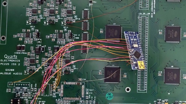
The 486 that [someyob] is restoring had the Turbo button, but sadly there was just a simple LED to show whether or not it was engaged. But there was a window in the front panel where it seemed like a numerical display was intended to go, so they decided to wire up their own CPU indicator by sensing the state of the Turbo LED with an Arduino Pro Mini.

Now to modern audiences, this might seem like cheating. After all, the Arduino isn’t actually measuring the CPU speed, nor is it directly controlling it (that’s still done by the original Turbo button wiring). But the truth is, even back in the day, the CPU frequency displays faked it — they just toggled between showing two predefined frequencies depending on the state of the button. The arrangement [someyob] has come up with does the same thing, except now there’s some extra processing power in the mix, so the display can show some slick animations as it switches between 33 and 66 Mhz.

In the GitHub repository, [someyob] has provided the Arduino source code and schematics showing how the microcontroller was shoehorned into the existing front panel wiring without compromising its functionality. There’s even a brief video below that shows the display in operation.

Like the idea but don’t have a 486 laying around? Don’t worry. We’ve seen a similar panel built for modern machines that  just doesn’t look the part, it actually manages to be functional.

Continue reading “486 Gets Animated Turbo Button Thanks To Arduino”

Building A Digital Compass With An Arduino

The magnetic compass has been a crucial navigational tool for around a thousand years or so, perhaps longer. While classical versions still work perfectly well, you can now get digital magnetometers that work in much the same way. [mircemk] decided to whip up a digital compass to demonstrate the value of these parts.

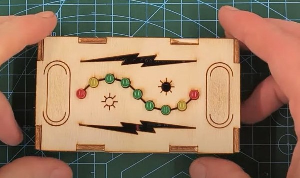
The build uses a HMC5883L magnetometer. While this can detect magnetic fields in three axes, just one is necessary for building a device that operates akin to a traditional compass. The output of the device is read by an Arduino Nano, which is hooked up to a string of WS2812B LEDs and a small OLED display. The LEDs display the bearing of magnetic north, while the OLED screen shows the current angle between the compass’s arrow and magnetic north.

It’s a tidy build that would be a great educational resource for teaching both electronics and navigational skills. We’ve seen similar projects before, like the hilarious Pizza Compass. Video after the break.

Continue reading “Building A Digital Compass With An Arduino”

Punched Cards Are In The Cloud, With This Arduino

Grizzled veterans of the computing industry will relate stories of submitting projects on stacks of punched cards, something those of us who stored their 8-bit works on audio cassettes could only imagine. But for those who fancy experimenting with the format it’s still possible to make a basic card reader using LEDs and light sensors, as [Nino Ivanov] has done using an Arduino Uno as the brains. And these aren’t just for show, each of his cards holds a LISP program that runs in a cloud service.

The Uno does the job of reading, passing its data over its USB serial port to a tablet. On the tablet the serial data is piped to a cloud API to a LISP interpreter. It seems a needlessly complex way to run a factorial program and it’s certainly a little over the top, but on the other hand we love it as a glorious combination of the old and the new. With only 23 characters per card it’s quite an impressive feat to even fit a program on the format, perhaps writing code to fit on minimalist punched cards like this could become a programming challenge in its own right for a generation accustomed to mega-and gigabytes.

If you fancy a go yourself, this isn’t the first punched card reader we’ve shown you.

Continue reading “Punched Cards Are In The Cloud, With This Arduino”

Arduino-Powered Missile System Uses Ultrasound To Aim

In the real world, missile systems use advanced radars, infrared sensors, and other hardware to track and prosecute their targets. [Raspduino Uno] on YouTube has instead used ultrasound for targeting for an altogether simpler desktop fire control solution.

This fun build uses a common off-the-shelf USB “missile launcher” that fires foam darts. To supply targeting data for the launcher, an Arduino Uno uses an ultrasonic sensor pair mounted atop a servo. As the servo rotates, the returns from the ultrasonic sensor are plotted on a screen run by a Raspberry Pi. If an object is detected in the 180-degree field of view of the sweeping sensor, a missile is fired using the dart launcher.

It’s a relatively simple build, but nonetheless would serve as a useful classroom demonstration of radar-like targeting techniques to a young audience. Real military hardware remains altogether more sophisticated. Video after the break.

Continue reading “Arduino-Powered Missile System Uses Ultrasound To Aim”

A Mega-Tiny Arduino

Integrated circuits, chipsets, memory modules, and all kinds of other transistor-based technology continues to get smaller, cheaper, and more energy efficient as time moves on. Not only are the components themselves smaller, but their supporting infrastructure is as well. Computers like the Raspberry Pi are about the size of a credit card and have computing power on the order of full-sized PCs from a few decades ago. The Arduino is no exception to this trend, either, and this new dev board called the Epi 32U4 might be the smallest ATmega platform we’ve seen so far.

As the name suggests, the board is based around the ATmega32U4 which is somewhat unique among Atmel chips in that it includes support for USB within the chip itself rather than relying on external translating circuitry. This makes it an excellent choice for any project which involves sending keyboard, mouse, or other peripheral information to a computer. This goes a few steps further with eliminating “bloat” compared to other boards, too — there’s no on-board voltage regulator, and just a single LEDs on pin 13.

One of the other features this board boasts over other small form factor boards is on-board USB-C, which is definitely a perk as more and more devices switch away from the various forms of older USB-type plugs. The project’s specifications are also available on this GitHub page for anyone that wants to produce their own. And, if you don’t have a 32U4 on hand and still want to build a keyboard project, it’s possible to get some other Arduinos to support these features but it’ll take a little more work.

Thanks to [Rasmus L] for the tip!

Decoding 433 MHz Signals With Arduino & Raspberry Pi

433 MHz radio signals are all around us. They’re used for things like smart power plugs, garage door openers, and home weather stations. Decoding these signals can allow you to interface and work with these devices on your own terms. To help in those efforts, [Joonas Pihlajamaa] has written a three-part tutorial on decoding these signals.

A soundcard makes for a very cheap oscilloscope.

The focus of the tutorials is decoding the signals of a Nexa radio-controlled smart plug. [Joonas] first explores using an Arduino to do the job, paired with a RFM210LCF-433D radio receiver module. This setup dumps out data to a computer over serial for decoding. [Joonas] then tried an alternative strategy, using a soundcard as a “poor man’s oscilloscope” to do the same job, using the same radio module and using Audacity for signal analysis. Finally, [Joonas] brought out the big guns, hooking up a Picoscope digital oscilloscope to a Raspberry Pi 4 for a more deluxe attempt at decoding the signals.

The tutorial goes to show that higher-end tools can make such a job much easier. However, the cheaper techniques are a great way of showing what can be done with the bare minimum in tools. We’re hoping for an exciting fourth part to [Joonas’s] work, where he instructs us on how to decode 433 MHz signals by drinking huge amounts of caffeine and staring at a very fast blinking LED. If you’ve got your own nifty signal analysis (or SIGINT!) hacks, be a good sport and drop them into the tipsline!


Arduino Does SDI Video With FPGA Help

If you are running video around your home theater, you probably use HDMI. If you are running it in a professional studio, however, you are probably using SDI, Serial Digital Interface. [Chris Brown] looks at SDI and shows a cheap SDI signal generator for an Arduino.

On the face of it, SDI isn’t that hard. In fact, [Chris] calls it “dead simple.” The problem is the bit rate which can be as high as 1.485 Gbps for the HD-SDI standard. Even for a super fast processor, this is a bit much, so [Chris] turned to the Arduino MKR Vidor 4000. Why? Because it has an FPGA onboard. Alas, the FPGA can’t do more than about 200 MHz, but that’s fast enough to drive an external Semtech GS296t2 serializer which is made to drive SDI signals.

The resulting project contains the Arduino, the serializer, a custom PCB, and both FPGA and microcontroller code. While the total cost of the project was a little under $200, that’s still better than the $350 to $2000 for a commercial SDI signal generator.

If you want to play along, the files are out on GitHub. We used the Vidor back in 2018 when it first came out. If you need a quick start on FPGAs, there’s always our boot camp.