Wax Motors Add Motion To Your Projects

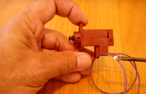
[electronicsNmore] has uploaded a great teardown and tutorial video (YouTube link) about wax motors. Electric wax motors aren’t common in hobby electronics, but they are common in the appliance industry, which means the motors can be often be obtained cheaply or for free from discarded appliances. Non-electric wax motors have been used as automotive coolant thermostats for years.  Who knows, this may be just what the doctor ordered for your next project.

As [electronicsNmore] explains, wax motors are rather simple devices. A small block of wax is sealed in a metal container with a movable piston. When heated, the wax expands and pushes the piston out. Once the wax cools, a spring helps to pull the piston back in.

The real trick is creating a motor which will heat up without cooking itself. This is done with a Positive Temperature Coefficient (PTC) thermistor. As the name implies, a PTC thermistor’s resistance increases as it heats up. This is the exact opposite of the Negative Temperature Coefficient (NTC) thermistors we often use as temperature sensors. PTC’s are often found in places like power supplies to limit in rush current, or small heating systems, as we have in our wax motor.

As the PTC heats up, its resistance increases until it stops heating. At the same time, the wax is being warmed, which drives out the piston. As you might expect, wax motors aren’t exactly efficient devices. The motor in  [electronicsNmore’s] video runs on 120 volts AC. They do have some advantages over solenoid, though. Wax motors provide smooth, slow operation. Since they are resistive devices, they also don’t require flyback diodes, or create the RF noise that a solenoid would.

Continue reading “Wax Motors Add Motion To Your Projects”

Hackaday Prize Finalist: An Un-noodly Spectrometer

And so we come to the final finalist bio for The Hackaday Prize. In only three days, we’ll know whether [fl@C@]’s RamanPi Spectrometer or one of the four other projects to make it into the finals round will be making it to space, or only Japan.

There are a surprising number of spectrometer projects out there on the Intertubes, but most of these setups only measure the absorption spectrum – literally what wavelengths of light are absorbed by the material being measured. A Raman spectrometer is completely different, using a laser to illuminate the sample, and measuring the scattering of light from the material. It’s work that has won a Nobel prize, and [fl@C@] built one with a 3D printer.

Bio below, along with the final video that was sent around to the judges. If you’re wondering who the winner of The Hackaday Prize is, even I don’t know. [Mike] and a few Hackaday overlords do, but the rest of us will remain in ignorance until we announce the winner at the party we’re having in Munich next Thursday.

Continue reading “Hackaday Prize Finalist: An Un-noodly Spectrometer”

Accurately Measuring Electrical Conductivity

[Ryan] designed a PCB that lets you easily take readings from a commercial electrical conductivity probe over I2C. Conductivity measurements are great for measuring the salinity of a solution, which is useful for applications like hydroponics. While the probes themselves are a bit pricey (on the order of $50 from eBay), they are very accurate and last a long time.

Commercial conductivity probes contain platinum electrodes to prevent corrosion. The electrodes are excited with an AC signal, which prevents polarization of the solution and avoids chemical reactions at the electrodes. The voltage across the two electrodes is measured while the electrodes are being excited, which is proportional to the conductivity of the solution

[Ryan]’s board generates +/-5v and uses a Wien bridge oscillator to generate a sine wave which excites the outermost electrodes. The voltage across the electrodes is amplified and fed into a MCP3221, an inexpensive 12-bit ADC with an I2C interface. [Ryan] also wrote an Arduino library for the MCP3221 so you can easily get your probe up and running.


RFToy Makes Wireless Projects Easier

[Ray] has created RFToy, a simple gadget to aid in setting up wireless systems with a variety of common radio modules. RFToy is an open source microcontroller board running on an ATmega328. While RFToy is Arduino code compatible, [Ray] chose to ditch the familiar Arduino shield layout for one that makes it easier to install RF modules, and is more handheld friendly.

[RFToy] includes headers for the popular nRF24L01 2.4 GHz transceiver, as well as 433/315 transmitters and receivers found in many low-cost wireless electronic devices. The 128×64 pixel OLED screen and 3 button interface make it easy to set up simple user interfaces for testing new designs.

[Ray] hasn’t broken any new ground here. What he has done is create a simple tool for wireless projects. Anyone who’s worked on a wireless system can tell you that tools like this are invaluable for debugging why your circuit isn’t talking. Is it the transmitter? The receiver? Something else in the power supply circuit?

Check out [Ray’s] demo video after the break. In it, he sniffs, records, and plays back signals from several remote-controlled outlets. [Ray] also has a great demo of sending temperature data back and forth using an nRF24L01.

Continue reading “RFToy Makes Wireless Projects Easier”

Developed On Hackaday: $50k Reached In A Week!

Around 500 awesome people backed the Mooltipass offline password keeper crowdfunding campaign, raising a total of $50k in less than a week… which is nearly half our goal.

The development team and I would therefore like to thank our readers for their support. We were featured by several electronics websites, which definitely helped spreading the world of open source security devices. Many interesting discussions spawned in either our comments section or official Google Group. One new contributor even started looking into implementing TOTP on the Mooltipass.

Another hot topic was a possible smaller and more powerful Mooltipass v2, implementing other functionalities like U2F and encrypted file storage. You may therefore wonder why we didn’t start with it… the reason is simple: limited resources. Our project is made by (great) non-remunerated contributors who took a lot of their spare time to work on the Mooltipass v1. We therefore preferred working on something we’d be sure we could deliver rather than wasting $4M by making promises. We therefore hope that our crowdfunding campaign might allow an even bigger collaboration around a Mooltipass v2!

An MSP430 Clone Of The Canon RC-1 Remote

For reasons we both agree with and can’t comprehend, most ‘prosumer’ SLR cameras don’t have mechanical shutter releases. Instead, IR LEDs are brought into the mix, the Canon RC-1 remote trigger being the shutter release of choice for people who didn’t choose Nikon. [Vicente] cloned the Canon RC-1, but he didn’t do it to save money; there’s a lot to learn with this project, and making his own allows him to expand it with more features in the future.

Studying the function of the Canon RC-1, [Vicente] found that some compromises needed to be made. The total power emitted by an IR LED is usually a function of its beamwidth; a smaller beamwidth means more photons reaching the IR receiver in the camera. This also means the remote must be aimed at the camera more accurately. In the end, [Vicente] decided on a higher power LED with a tighter beamwidth that’s just slightly below the optimum wavelength for the receiver. It’s all an exercise in compromise, but other components could see similar performance.

With the LED selected, [Vicente] moved on to building the actual controller. He chose an MSP430 microcontroller for its low power consumption, driving the LED with a watch battery and a transistor. Put together on a piece of protoboard, it’s actually pretty close to a TV-B-Gone. With everything soldered up, it’s good enough to trigger his camera’s shutter from about 5 meters away. Future improvements include cleaning up the code, making the timing more accurate with a crystal, and implementing low power mode on the MSP430.

The Raspberry Pi Model A+

A few months ago we were lucky to get the scoop on a new Raspberry Pi a few days before it was officially announced. This model ended up being the Raspberry Pi Model B+, with improvements that included more USB ports, not-dumb mounting holes, more GPIOs, and a decent microSD card connector. Today, we’re proud to leak another revision to the Raspberry Pi ecosystem – the Raspberry Pi Model A+

There really aren’t many details for this new revision of the Raspi, but we can make some educated guesses. The new model features the same not-dumb mounting holes as the B+, 58mm wide by 49mm wide. All the ports are moved to two sides of the board, and the analog audio and video are combined into one 3.5mm jack. Like the normal Model A, this one doesn’t have Ethernet and only one USB port, but the improvements seen from the B to the B+ are still there: a good microSD card socket is on the back, and the 40-pin GPIO header replaces the old 26-pin header. There’s no word if the A+ will feature a RAM upgrade – when the Model B was ramping up production The Foundation decided to bump the RAM up to 512MB. This could happen with the A+, but we’re not holding our breath.

There’s no word when the A+ will be announced, or when it will start shipping. The educated guess would say tomorrow morning, with an analysis of how much power this thing consumes a week after it starts shipping.