Although easily dismissed by some as another cruel April Fools joke, Raspberry Pi’s announcement of a new 3 GB model of the Raspberry Pi 4 along with (more) price increases for other models was no joke. Courtesy of the ongoing RAMpocalypse, supplies of LPDDR4 and LPDDR5 are massively affected, leading to this new RPi 4 model with two 1.5 GB LPDDR4 chips, as these are apparently cheaper to source.
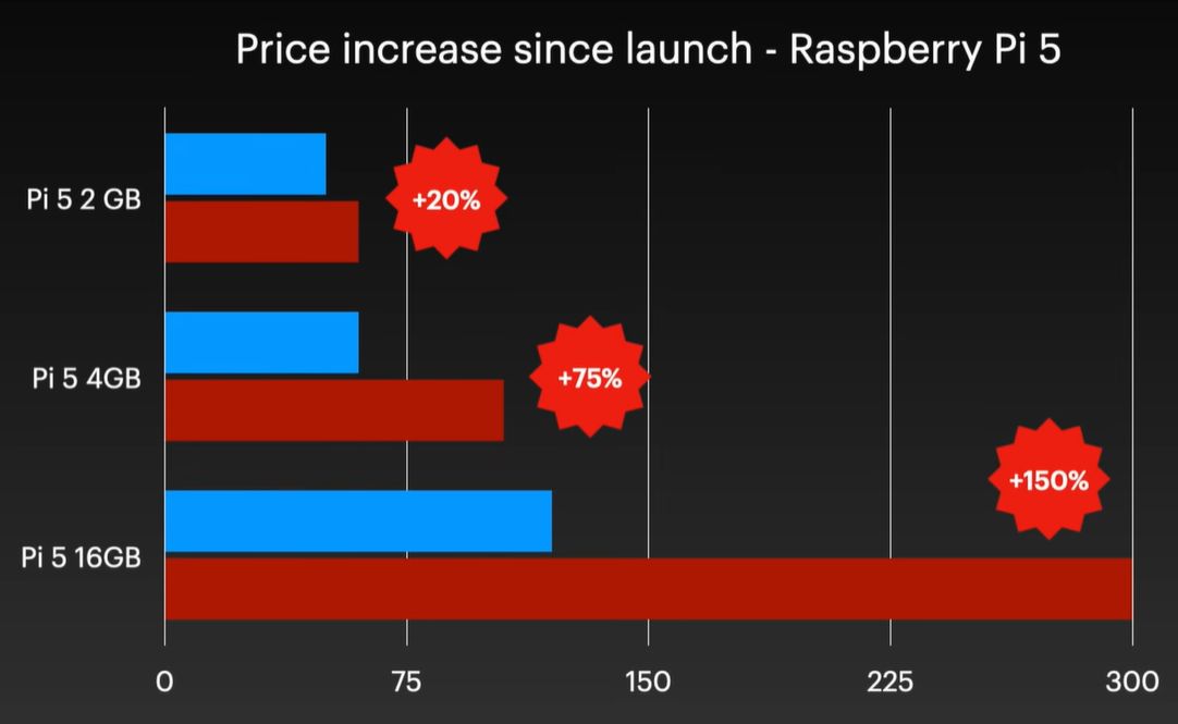
Affected in this latest price increase across RP’s product range are RPi 4 and 5 models with 4 or more GB of RAM, with price bumps ranging from $25 on the low end to $150 for the Raspberry Pi 500+. If you wanted a Raspberry Pi 5 with 16 GB of RAM, you’re now paying $300 for the privilege.
Obviously, this news has got people like [Jeff Geerling] rather down in the dumps, essentially stating that using SBCs like the RPi is now beyond the means of many hobbyists. While you can still use SBCs that use e.g. LPDDR2 RAM, such as the older RPi Zero, 2 and 3 models, [Jeff] himself is now moving more towards wrangling with snakes on MCUs, as these boards are so far not significantly affected in terms of price.
With current projections in the RAM market being that this year will still see more price increases, it remains hard to tell exactly how ‘temporary’ this situation will be. That said, using readily available, powerful and cheap MCUs like the ESP32 variants for projects isn’t a bad idea if you really don’t need to be running more than perhaps FreeRTOS.
Continue reading “The Raspberry Pi 4 With 3 GB RAM Is No Joke”