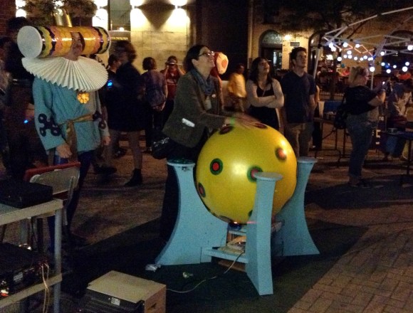
A Pair Of Automatic Fish Feeders

a-pair-of-automatic-fish-feeders

Sometime the hacking topics come in waves. For instance, we were tipped off about this pair of automatic fish feeders just an hour apart from each other. Maybe it’s that time of year when people are about to go on Holiday and want to make sure their marine pets don’t go hungry?

The feeder on the left is a true hack. It’s built from a pair of servos and a pill bottle. An ATtiny85 drives the motors. One is mounted to the other, allowing the cap which catches and distributes the food to move along two axes. When it rotates into place under the pill bottle it bumps against a stick to open a flapper releasing more food.

On the right is a feeder that precisely doses the food. That’s because it includes a separate chamber for each feed. A worm gear drives the hopper, with screw heads pressing against a leaf switch for position feedback. This one is well designed and built to last.

Programming A 555 Chip

555

[Phillip] needed a way to trigger an input every 8 hours or so. This is a snap with a microcontroller with a proper timer, but he recently heard about a very cool programmable timer chip that’s also a 555. Of course CSS555 timer chip has an obscure programming interface, but that isn’t a problem when you can program it yourself with a parallel port.

The CSS555 timer chip (PDF…) is a strange little beast. It’s pin compatible with everyone’s favorite timer IC, but also has a programming mode that allows the output to trigger on every 1 cycle, every 10 cycles, and so on up to one output every million cycles. Basically, it’s a 555 with a huge programmable capacitor that only costs two bucks.

After building a programming circuit from a 74125 hex buffer chip, [Philip] connected his programmer to the parallel port of an ancient PC. For a little retrocomputing cred, he wrote a small app in Forth that pushes commands from the parallel port to the CSS555 chip, greatly increasing the time delay of the chip’s stock configuration.

It’s a neat build, and an awesome introduction to a really cool timer chip. Of course this could be easily replicated with a $2 microcontroller, but that wouldn’t give [Philip] the satisfaction of using a 555.

Building A Tool To Measure Melting Point

melting-point-apparatus

When working with chemical reactions it may be necessary to test the purity of the components you’re using. This is especially true with hobby chemists as they often acquire their raw materials from the hardware store, garden center, or pool supply. [Ken] figured out how to get around the $500 price tag of a commercial unit by building this DIY melting point test apparatus.

In this image he’s using a thermocouple to monitor the temperature of the melting surface, but mentions that you can do this with an inexpensive dial thermometer and will still have great results. That melting surface is the hexagonal head of a bolt which he drilled out to provide a concave surface for the test compound. Inside the PVC pipe is the heating element from a 40W hot glue gun. He wrapped it in fiberglass fabric which is sold in the plumbing supply to protect the area around pipe joints during soldering. The rotary light dimmer feeds the electricity to the element, allowing for adjustments to the ramping speed.

Raspberry Pi Is Right At Home Inside Of A Game Boy

IMG_20130201_163325

[Matt] still has his original Game Boy from when he was a kid. He wanted to pull it out and play some of the classics but alas, the screen was broken and he couldn’t find a source for a drop-in replacement. In the end he ordered a used unit and pulled the screen from that one. This left him with a pile of leftover Game Boy parts which turned into a Raspberry Pi case project.

Since the RPi doesn’t have a power switch he thought it would be pretty neat to incorporate the Game Boy power switch. He was able to cut out one section of the original PCB that included the switch and one mounting hole. This kept the switch aligned with the case and gave him some pads to solder the incoming USB cable and the jumper wires to the RPi board. In the image above the power LED is on. He mentions that there was an issue with that circuit; the voltage drop across the LED was messing up the feed to the Pi so it’s disabled for now.

We’ve embedded a couple of images of everything inside the case after the break. If you’re a fan of this hack you should also take a look at the Game Boy hard drive enclosure which uses the same pixel art printed on paper effect for the screen window.

Continue reading “Raspberry Pi Is Right At Home Inside Of A Game Boy”

3D Printed Prosthetic Hand Helps Out For About $150

3d-printed-prosthetic-hand-on-thingiverse

We know that there are already 3D printed hips and knees in use in the medical field, but it takes a story like this one to really bring home the idea of how this technology changes lives. 5-year-old [Liam] is missing parts of his right hand, and this open-source prosthetic hand has given him a jolt of increased function. The video clip after the break shows him on the third day with the device. He’s practicing picking up coins from a stack using the hand. Just $150 in parts, combined with the hard work and good nature of the developers, made this possible.

The design is available on Thingiverse. In addition to the 3D printed parts the prosthesis uses off-the-shelf hardware store items like bungee cord and fasteners. The tips of each finger and the thumb are given some flex and grip by covering each with a rubber thimble.

We love seeing this life-changing technology wielded by basement and garage hackers. Another great example is this scratch-built leg from last May.

Continue reading “3D Printed Prosthetic Hand Helps Out For About $150”

A Constant Resistance Dummy Load Design

constant-resistance-dummy-load

This constant resistance dummy load has not yet been tested in the real world. [YS] was inspired to come up with the circuit after reading Wednesday’s Re:load dummy load post. That was a constant current load, not a constant resistance load. [YS] started with the schematic for the Re:load and made his changes to arrive at this.

For him the exercise was just to alter the design to achieve constant resistance. He didn’t actually build and test the hardware because he doesn’t really have a need for it. This image was exported from Proteus, which includes a ProSPICE circuit emulator. His slides run through test voltages from 5V to 50V, maintaining a constant 10 Ohm resistance.

When studying this project we needed a little refresher on the different varieties of dummy loads. We found this post very informative about the differences and uses of Constant Current, Constant Power, and Constant Resistance (Impedance) loads.

Learn Shift Registers Without Involving A Microcontroller

This is a truly hands-on approach to learning. [Kevin Darrah] ditched the microcontroller and is using push buttons to learn about 595 shift registers. The test rig uses two of the serial-in, parallel-out chips. These are cascading which means that as data from the first chip overflows it feeds the input of the second. The parts are commonly used to drive LEDs, or reduce the number of pins needed to drive peripherals like this character LCD.

The five push-buttons give you a chance to intuitively learn how the chip logic works. The blank button is also commonly called Output Enable (OE). Driving it high shuts off the outputs of the chips but doesn’t clear the data. That task is performed by the clear button which is driven low to set all of the shift register memory to zero. The other three buttons set the logic level, shift it into the chip using the clock signal, and push the stored values to the outputs using the latch.

To get a visual approximation of what’s happening inside of these chips you should check out the shift register tutorial linked to in this post.

Continue reading “Learn Shift Registers Without Involving A Microcontroller”